Circuit tester

Inactive Publication Date: 2006-09-05
SHORT BARRY W F
View PDF19 Cites 30 Cited by
  • Summary
  • Abstract
  • Description
  • Claims
  • Application Information

AI Technical Summary

Benefits of technology

[0014]It is another object of the present invention to provide a device for testing the continuity or integrity of a circuit which will remain securely in place but which can be easily placed and/or removed when desired.
[0015]These, and other, objects are achieved by a circuit continuity tester that includes a housing that is sized and adapted to snugly fit into a light bulb socket. Spring-loaded prongs on the housing make it easy to insert the housing into the light bulb socket, but will securely hold the housing in place once it is in the socket. The housing can be easily removed from the socket by manipulating

Problems solved by technology

This can be a very time-consuming operation, especially when it must be performed by one person working alone.
If the tester bec

Method used


Image

  • Circuit tester
  • Circuit tester

Examples


Embodiment Construction

[0020]Other objects, features and advantages of the invention will become apparent from a consideration of the following detailed description and the accompanying drawings.

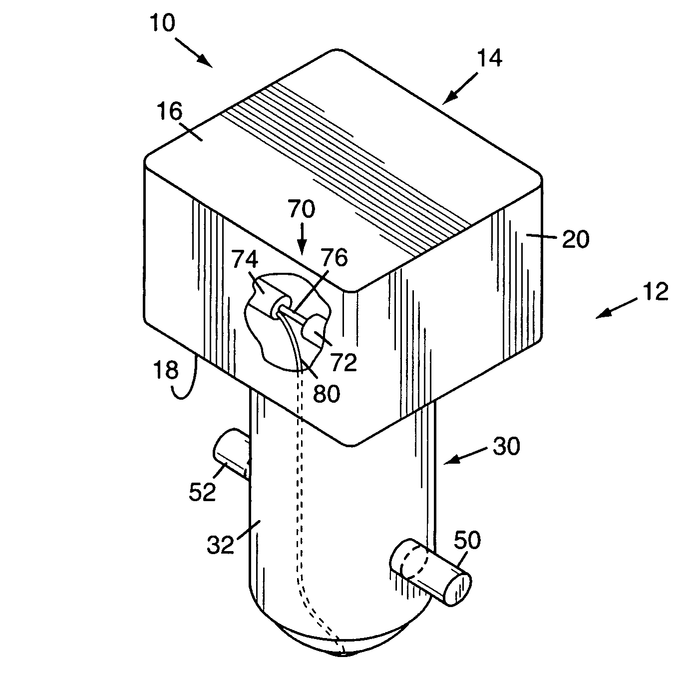
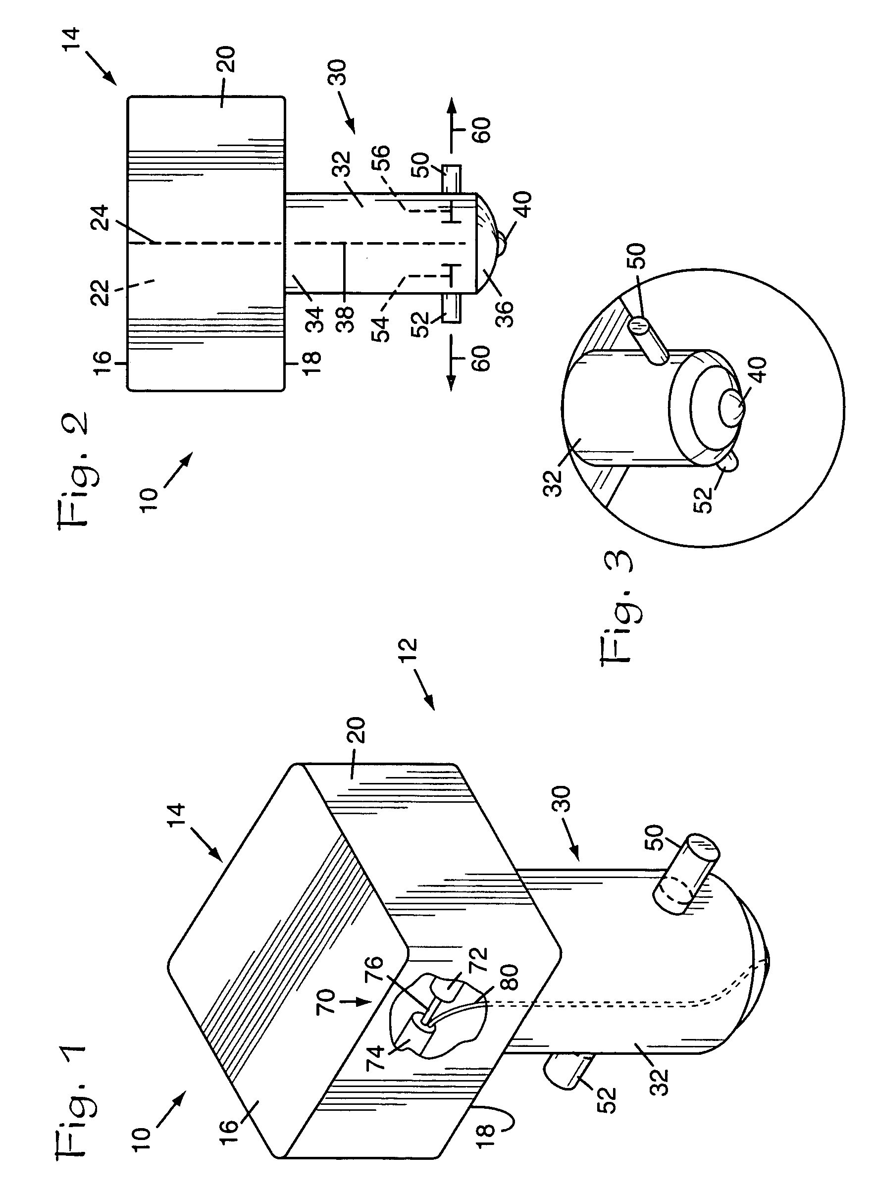
[0021]Referring to the Figures, it can be understood that the present invention is embodied in a circuit tester 10 that achieves the above-stated objectives.

[0022]Circuit tester 10 comprises a housing 12 which has a first section 14 that is a top section when housing 12 is in use, with the use position being shown in FIG. 1. Top section 14 includes a first surface 16 that is a top surface when housing 12 is in use and a second surface 18 that is a bottom surface when housing 12 is in use. A plurality of side walls, such as side wall 20, connect first surface 16 to second surface 18.

[0023]An interior volume 22 is defined by first surface 16, second surface 18, and the side walls 20 of first section 14 of housing 12. A longitudinal axis 24 extends between first surface 16 and second surface 18 of housing 12.

[0024]Ho...


PUM


Abstract

A circuit testing device includes a housing that is sized and adapted to securely fit into a light bulb socket. The device includes spring-loaded prongs which securely hold the housing in place in the socket until it is desired to remove the testing device. The testing device generates an audible signal when power is applied to the socket to alert a user that power is present, even if the user is located at a distance from the point of test.

Description

BACKGROUND OF THE INVENTION[0001]1. Field of the Invention[0002]The present invention relates to means for testing electrical circuits, and more particularly to testing for power in electrical circuits.[0003]2. Description of the Related Art[0004]In the service wiring of virtually any modern commercial or residential building, an incoming AC power line is connected to a fuse box or other circuit-breaking means for protection in the event a circuit is loaded beyond a desired amperage. Normally the structure is wired with a plurality of separate, electrically distinct circuits each connected to a different fuse or circuit breaker. Each circuit may, and commonly does, include a number of receptacles or other outlets for selectively connecting the items to receive electrical power from the circuit.[0005]Many situations arise which make it necessary to determine in which circuit a particular outlet is connected, where this is not otherwise indicated. This can be a very time-consuming ope...

Claims


Application Information

Patent Timeline
IPC IPC(8): G01R31/04G01R19/145G08B21/00
CPCG01R19/155G01R1/06788
Inventor SHORT, BARRY W. F.
Owner SHORT BARRY W F
Why Eureka
Try Eureka