Use of smart antenna in beam formation circuit

Inactive Publication Date: 2006-09-05
KK TOSHIBA
View PDF5 Cites 132 Cited by
  • Summary
  • Abstract
  • Description
  • Claims
  • Application Information

AI Technical Summary

Benefits of technology

[0022]A still further aspect of the present invention provides a method of receiving radio frequency signals by the use of a smart antenna capable of adjusting its directivity by making use of a plurality of antenna elements, said method comprising: a step of intermittently extracting pilot sub-carrier signals from a serial signal containing a time series data sequence as Fo

Problems solved by technology

In this case, however, a large amount of computation tasks are necessarily required to obtain the weights of all the sub-carriers of the OFDM system.
For this reason, the excessive amounts of processing power and computation time become obstacles to the operation of the system, for example, in the case where voice signal processing is required in real time.
Furthermore, since all

Method used


Image

  • Use of smart antenna in beam formation circuit
  • Use of smart antenna in beam formation circuit
  • Use of smart antenna in beam formation circuit

Examples


second embodiment

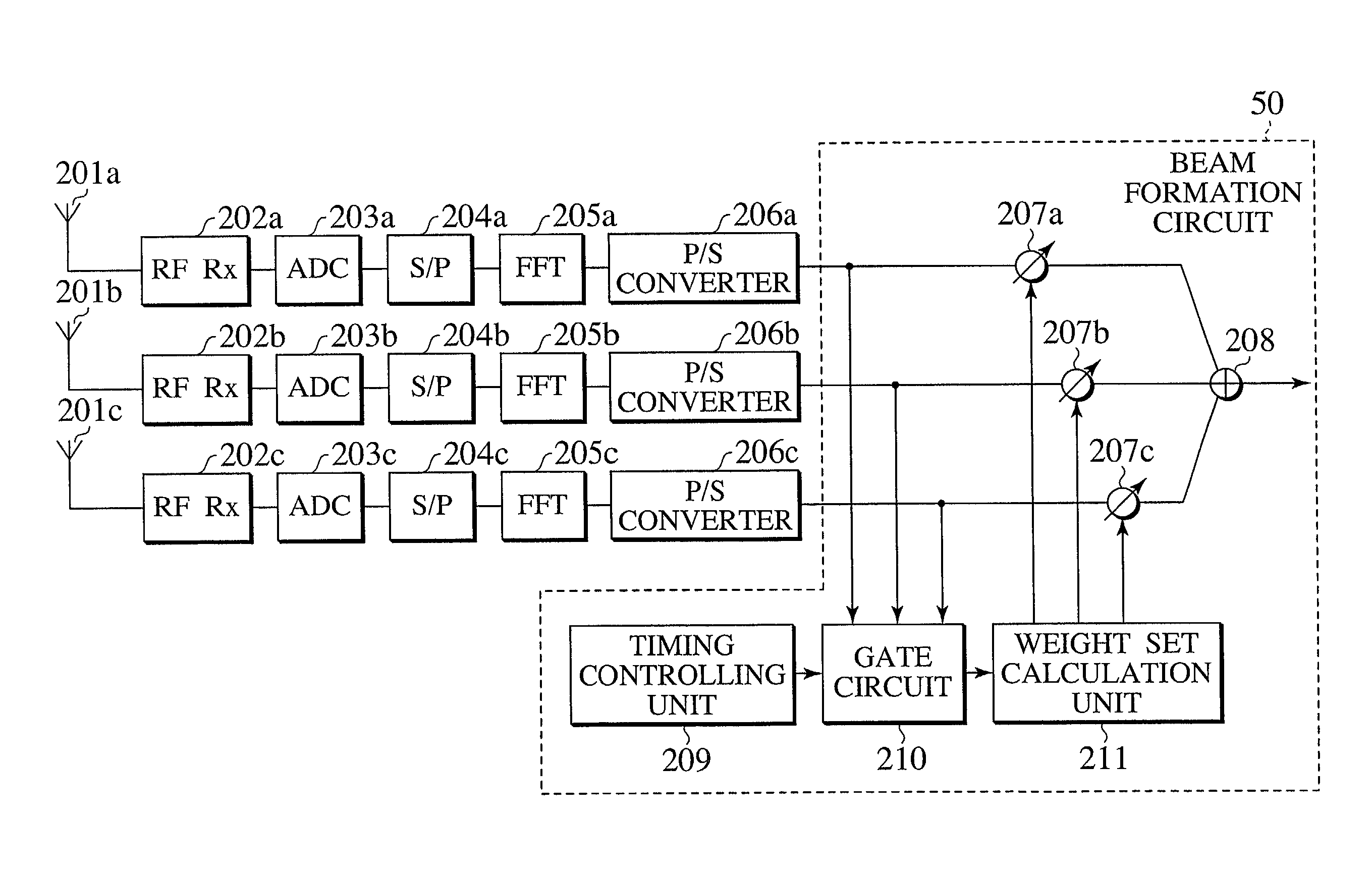
[0044]FIG. 6 is a block diagram showing the receiver apparatus provided with a smart antenna in accordance with the present invention. The receiver apparatus of the present embodiment is provided with antenna elements 201a to 201c, high frequency wave reception circuits (RF RX) 202a to 202c serving to perform necessary processes of wireless frequency signals as received, i.e., filtering, low-noise amplification, frequency conversion and so forth, orthogonally demodulation and so forth, A / D converters (ADC) 203a to 203c for converting analog signals at the base band frequency to digital signals, FFT units 205a to 205c for performing the fast Fourier transformation of the digital signals, S / P converters 204a to 204c for performing serial-to-parallel conversion of the digital signals in advance of the FFT unit 205a to 205c, P / S converters 206a to 206c for performing parallel-to-serial conversion of the digital signals after the FFT unit 205a to 205c, a pilot signal extraction unit (Gat...

first embodiment

[0046]On the other hand, the pilot signal extraction unit 210 serves to intermittently extract signals on the pilot sub-carriers from the output signals of the FFT units whereas the weight set calculation unit 211 serves to calculate an appropriate antenna weight set for each sub-carrier group in order to form a desired directivity pattern. In this case, the timing controlling unit 209 serves to detect the input / output signal timing at the FFT units and to control the signal timing required for extracting signals on the pilot sub-carriers from all the output signals of the FFT units. Also, the respective antenna weights are calculated on the basis of one of a variety of beam formation algorithms in the same manner as in the present invention.

[0047]The antenna weight sets as calculated are multiplied by the respective received signals by means of the weighting units 207a and combined together by means of the adder circuit 208. By this configuration, signals are obtained with a desire...

third embodiment

[0053]FIG. 8 is a block diagram showing the receiver apparatus provided with a smart antenna in accordance with the present invention. The receiver apparatus of the present embodiment is provided with antenna elements 401a to 401c, high frequency wave reception circuits (RF RX) 402a to 402c serving to perform necessary processes of wireless frequency signals as received, i.e., filtering, low-noise amplification, frequency conversion and so forth, orthogonally demodulation and so forth, weighting units 404a to 404c for weighting signals of the sub-carriers with the corresponding antenna weights, an adder circuit 405 for combining together the signals of the three paths as weighted, an S / P converter 406 for converting the combined signals as weighted into the parallel signals, an FFT unit 407 for performing the fast Fourier transformation of the parallel signals, a P / S converter 408 for converting the parallel signals after the fast Fourier transformation into the serial signals, a ti...


PUM


Abstract

A beam formation circuit and an apparatus and a method of receiving radio frequency signals making use of a smart antenna are described in which the amount of computation tasks required for the weight calculation is significantly reduced. In realizing the directivity of the smart antenna, the output signals corresponding to a plurality of sub-carriers are weighted with a common antenna weight for each of the antenna elements.

Description

CROSS REFERENCE TO RELATED APPLICATIONS[0001]This application is based upon and claims the benefit of priority from prior Japanese Patent Application P2000-391221 filed on Dec. 22, 2000; the entire contents of which are incorporated by reference herein.BACKGROUND OF THE INVENTION[0002]1. Field of the Invention[0003]The present invention relates generally to a wireless communication system in accordance with Orthogonal Frequency Division Multiplexing, and particularly to a beam formation circuit and an apparatus and a method of receiving radio frequency signals making use of a smart antenna a receiver apparatus.[0004]2. Description of the Related Art[0005]In recent years, with the high speed advent of the wireless communication technique, wireless terminals have been used by end users for the purpose of receiving and transmitting a large amount of information such as images, other types of data, in addition to voices. It is inevitable for high speed transmission of such a large amoun...

Claims


Application Information

Patent Timeline
IPC IPC(8): H04B7/10H04L1/02H01Q1/24H01Q3/26H04B7/08H04J11/00H04L27/26
CPCH01Q1/246H04L27/2647H04B7/086H01Q3/2605
Inventor MATSUOKA, HIDEHIROOBAYASHI, SHUICHI
Owner KK TOSHIBA
Why Eureka
Try Eureka