Hearing aid having second order directional response

a hearing aid and directional response technology, applied in the field of microphone systems, can solve the problems of large research expenditure, difficult to understand conversational speech in background noise, severe signal-to-noise ratio problems, etc., and achieve the effect of increasing sensitivity and increasing hearing aid performan

Inactive Publication Date: 2006-09-05
ETYMOTIC RES
View PDF29 Cites 45 Cited by
  • Summary
  • Abstract
  • Description
  • Claims
  • Application Information

AI Technical Summary

Benefits of technology

[0009]It is an object of the present invention to provide an improved speech intelligibility in noise to the wearer of a small in-the-ear hearing aid.
[0010]It is a further object of the present invention to provide the necessary mechanical and electrical components to permit practical and economical second-order directional microphone constructions to be used in head-worn hearing aids.
[0011]It is a still further object of the present invention to provide a switchable noise-reduction feature for a hearing aid whereby the user may switch to an omni-directional microphone for listening in quiet or to music concerts, and then switch to a highly-directional microphone in noisy situations where understanding of conversational speech or other signals would otherwise be difficult or impossible.
[0012]It is a still further object of the present invention to provide an automatic switching function which, when activated, will automatically switch from the omni-directional microphone to a directional microphone whenever the ambient noise level rises above a certain predetermined value, such switching function taking the form of a “fader” which smoothly attenuates one microphone and brings up the sensitivity on the other over a range of overall sound levels so that no click or pop is heard.
[0014]Several switching circuit embodiments are set forth. In one embodiment, the switching circuit is manually actuatable by a wearer of the hearing aid. In a further embodiment, the switching circuit is operated automatically in response to the level of sensed ambient noise to switch directly between the first and second switching states. In a still further embodiment, the switching circuit is operated automatically as a fader circuit in response to the level of sensed ambient noise to gradually switch between the first and second states thereby providing a gradual transition between the microphones.
[0016]In one embodiment of the invention, the directional microphone is of the second order. The second order microphone is constructed from two first order gradient microphones that have their output signals subtracted in a subtracter circuit. The output of the subtracter circuit provides a second order directional response. Optionally, diffraction scoops may be disposed over the sound ports of the first order gradient microphones to increase their sensitivity. Hearing aid performance may be further increased by employing a windscreen in addition to the diffraction scoops.

Problems solved by technology

Individuals with impaired hearing often experience difficulty understanding conversational speech in background noise.
In some cases, the background noise may be more intense than the target speech, resulting in a severe signal-to-noise ratio problem.
The approach, however, requires very large research expenditures, and, at present, large energy expenditures.
Such digital signal processing schemes therefore hold little immediate hope for the hearing aid user.
First-order directional microphones, however, are not without their drawbacks when utilized in the in-the-ear hearing aids employed by some 75% of hearing aid wearers.
An additional problem with directional microphones in head-worn applications is that the improvement they provide over the normal omni-directional microphone is less than occurs in free-field applications because the head and pinna of the ear provide substantial directionality at high frequencies.
The problem with this array approach is that the Soede array is 10 cm long, requiring eyeglass-size hearing aids.
It is certainly not practical for the in-the-ear hearing aids most often used in the United States.
While there may be many individuals whose loss is so severe that the improved signal-to-noise obtained with such a head-worn array would make it attractive, a majority of hearing aid wearers would find the size of the array unattractive.
Second-order directional microphones, however, have always been considered impractical because their sensitivity is so low.
The steady hiss of such amplified microphone noise is objectionable in a quiet room, and hearing aids with equivalent noise levels more than about 10-15 dB greater than that obtained with an omni-directional microphone have been found unacceptable in the marketplace.
For similar reasons, first order microphones have likewise not gained wide acceptance for use in hearing aids.

Method used


Image

  • Hearing aid having second order directional response
  • Hearing aid having second order directional response
  • Hearing aid having second order directional response

Examples


Embodiment Construction

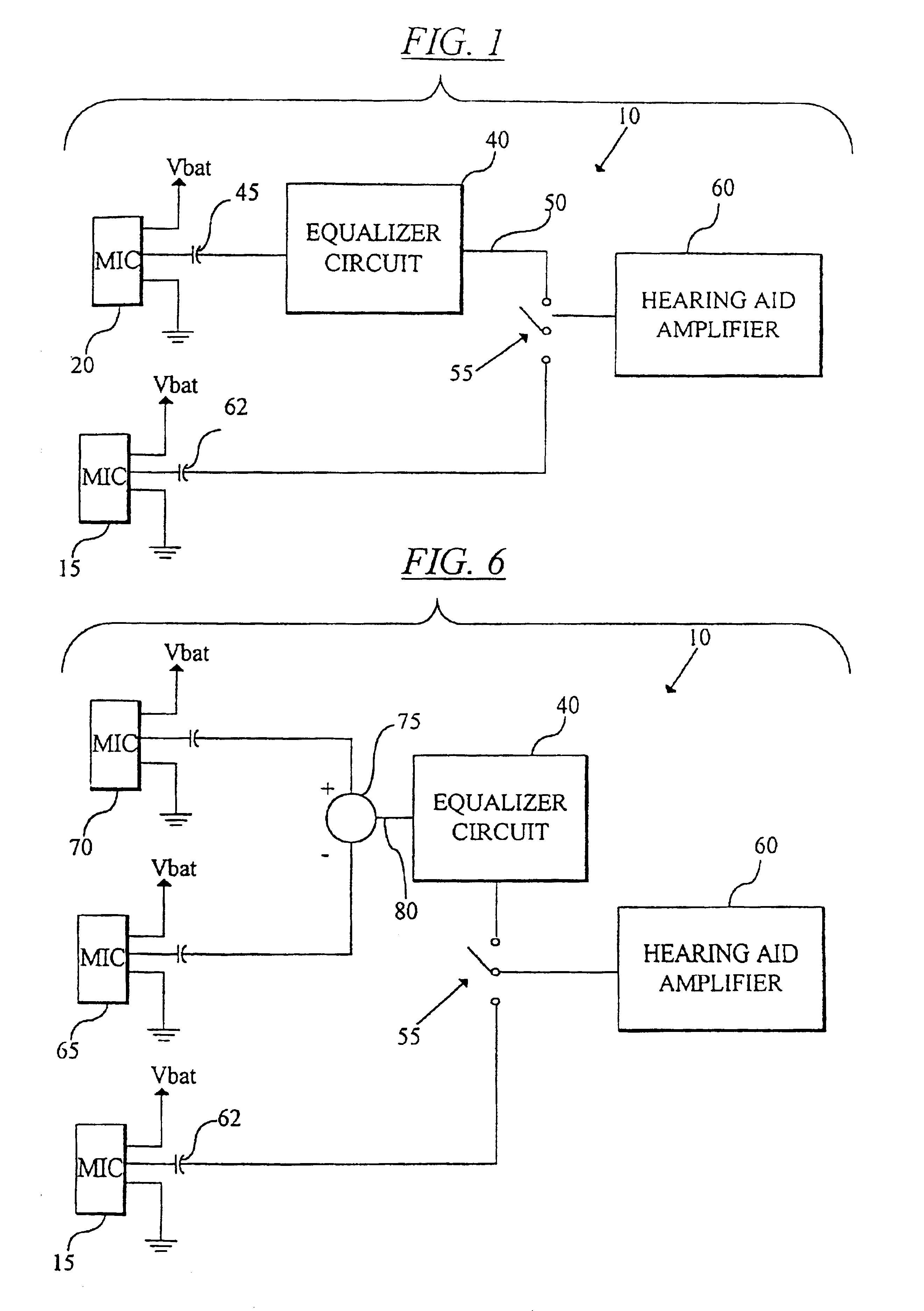
[0036]A hearing aid apparatus constructed in accordance with one embodiment of the invention is shown generally at 10 of FIG. 1. As illustrated, the hearing aid apparatus 10 utilizes both an omnidirectional microphone 15 and a directional microphone 20 of at least the first order. Each of the microphones 15,20 is used to convert sound waves into electrical output signals corresponding to the sound waves.

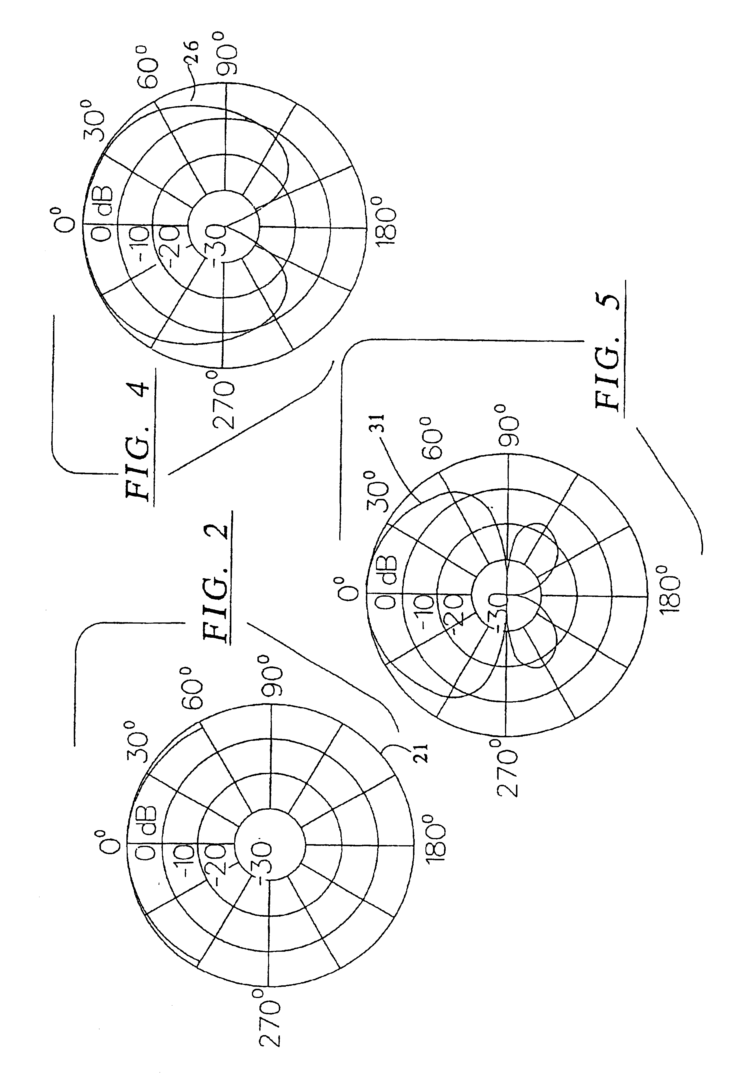
[0037]The free space directional response of a typical omnidirectional microphone is shown by line 21 in FIG. 2 while the corresponding frequency response of such a microphone is shown by line 25 of FIG. 3. The directional and frequency response of a typical omnidirectional microphone make it quite suitable for use in low noise environments when it is desirable to hear sound from all directions. Such an omnidirectional microphone is particularly suited for listening to a music concert or the like.

[0038]The free space directional response of one type of a first order directional micro...


PUM


Abstract

A hearing aid apparatus is disclosed that employs both an omnidirectional microphone and at least one directional microphone of at least the first order. The electrical signals output from the directional microphone are supplied to an equalization amplifier which at least partially equalizes the amplitude of the low frequency electrical signal components of the electrical signal with the amplitude of the mid and high frequency electrical signal components of the electrical signals of the directional microphone. A switching circuit accepts the signals output from both the omnidirectional microphone and the directional microphone. The switching circuit connects the signal from the omnidirectional microphone to an input of a hearing aid amplifier when the switching circuit is in a first switching state, and connects the output of the equalization circuit to the hearing aid amplifier input when the switching circuit is in a second switching state. The switching circuit may be automatically switched in response to sensed ambient noise levels.

Description

CROSS-REFERENCE TO RELATED APPLICATIONS[0001]This application is a continuation of U.S. application Ser. No. 09 / 624,805 filed Jul. 24, 2000, which is a continuation of U.S. application Ser. No. 08 / 955,271 filed Oct. 21, 1997, now U.S. Pat. No. 6,101,258 issued Aug. 8, 2000, which is a continuation of U.S. application Ser. No. 08 / 632,517 filed Apr. 12, 1996, now abandoned, which is a continuation of U.S. application Ser. No. 08 / 046,241 filed Apr. 13, 1993, now U.S. Pat. No. 5,524,056 issued Jun. 4, 1996.INCORPORATION BY REFERENCE[0002]U.S. Pat. No. 5,524,056, U.S. Pat. No. 6,101,258 and U.S. application Ser. No. 09 / 624,805 are hereby incorporated herein by reference in their entirety.STATEMENT REGARDING FEDERALLY SPONSORED RESEARCH OR DEVELOPMENTFIELD OF THE INVENTION[0003]This invention relates to improvements in the use of directional microphones for hearing aids that are used in circumstances where the background noise renders verbal communication difficult. More particularly, the...

Claims


Application Information

Patent Timeline
Patent Type & Authority Patents(United States)
IPC IPC(8): H04R25/00H04R3/00H04R29/00
CPCH04R29/006H04R25/43H04R25/407H04R3/005H04R29/005
Inventor KILLION, MEAD C.
Owner ETYMOTIC RES
Why Eureka
Try Eureka