System and method for predicting component failures in large systems

a technology of large systems and components, applied in the field of prediction systems, can solve the problems that each of the components comprising these systems may have non-uniform degradation rates

Active Publication Date: 2006-09-05
GENERAL ELECTRIC CO
View PDF9 Cites 59 Cited by
  • Summary
  • Abstract
  • Description
  • Claims
  • Application Information

AI Technical Summary

Problems solved by technology

In addition, each system belonging to such a fleet of systems may be of different ages, may have non-uniform degradation rates and furthermore, each of the components comprising these systems may themselves have non-uniform degradation rates.

Method used


Image

  • System and method for predicting component failures in large systems
  • System and method for predicting component failures in large systems
  • System and method for predicting component failures in large systems

Examples


Embodiment Construction

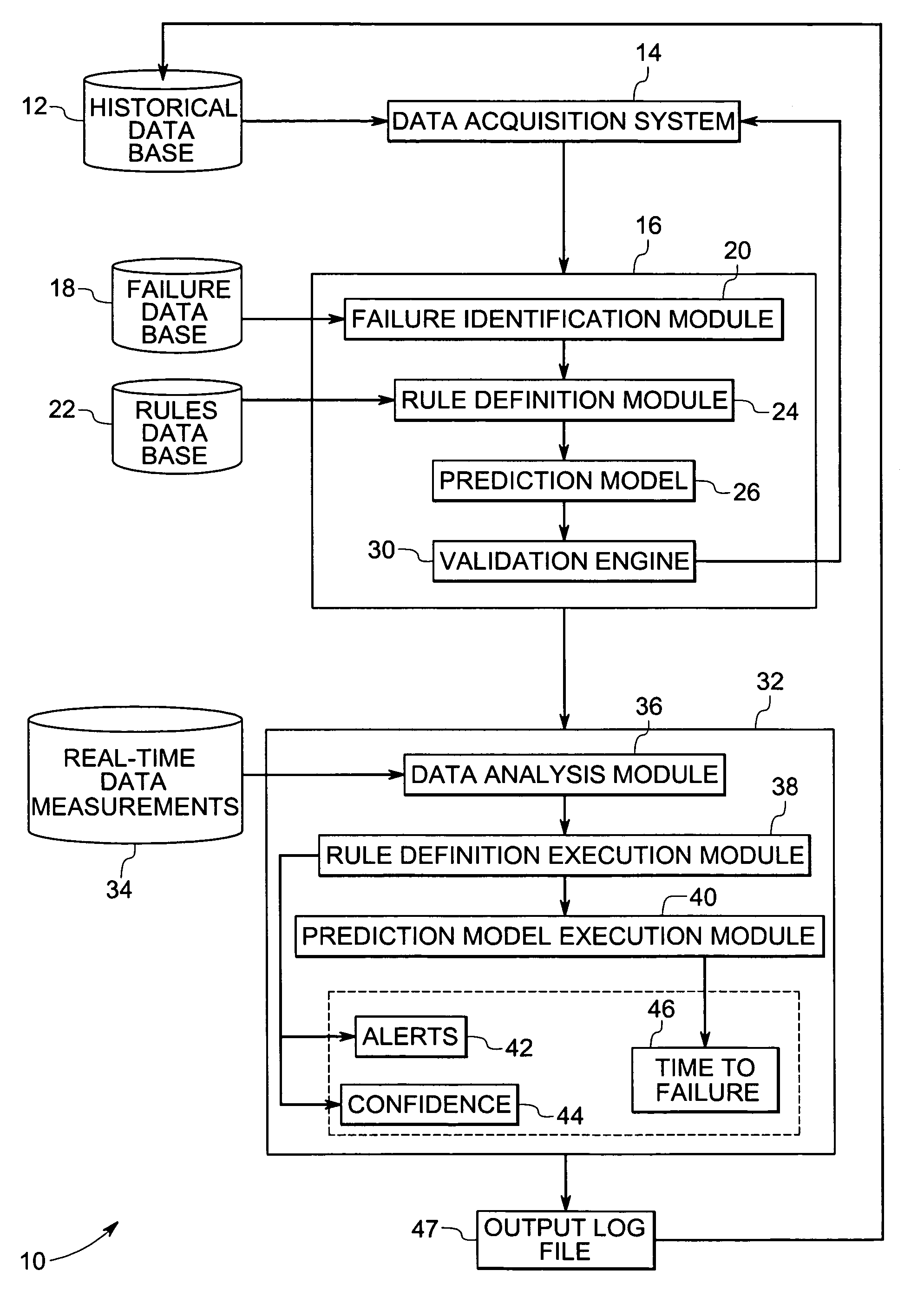
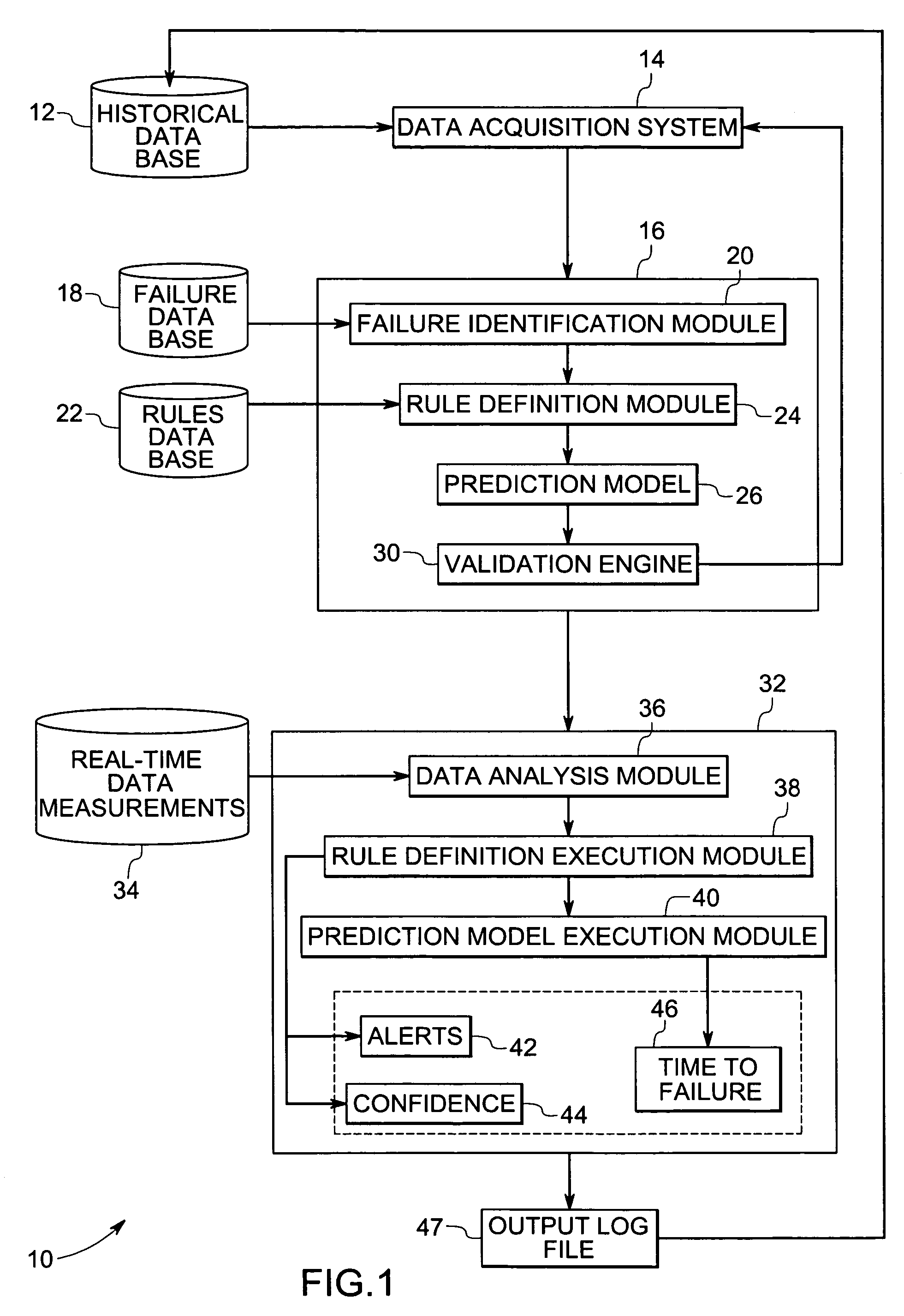
[0013]Disclosed herein, is a system and method for predicting the time to failure of components that are a part of large systems. Embodiments of the present invention disclose a prediction system that takes into consideration non-uniform component degradation rates of large systems that are a part of a fleet of systems. In addition, the disclosed prediction system effectively predicts the individual time to failure of selected components belonging to such a fleet of systems, as will be described in greater detail below. Embodiments of the present invention offer many advantages, including facilitating predictive maintenance, reducing maintenance costs, reducing component downtime and preventing component failure and system shutdown.

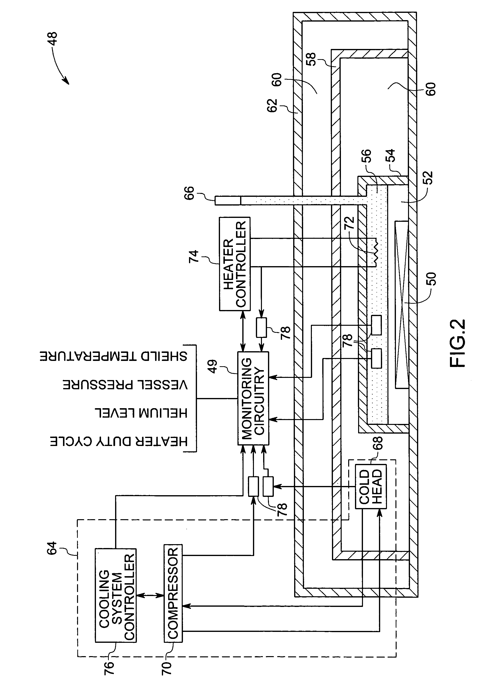
[0014]In one embodiment of the present invention, and as will be described in greater detail below, the large system is an imaging device such as, for example, a Magnet Resonance Imaging (MRI) device or a Nuclear Magnetic Resonance (NMR) imaging device. I...


PUM


Abstract

A method for predicting a time to failure of a component in a system is presented. The method comprises obtaining a set of data measurements related to the component. The set of data measurements are representative of a plurality of parameters including a plurality of leading parameters. The method comprises generating a prediction model based upon the leading parameters considered in combination. The prediction model is then used to predict the time to failure of the component based on a set of real-time measurements, wherein the plurality of parameters are processed to predict the time to failure for the component. Finally, a confidence level for the predicted time to failure is determined based upon the plurality of parameters.

Description

BACKGROUND[0001]The invention relates generally to prediction systems and more particularly to a system and method for predicting component failures in large systems.[0002]A large system may be considered generally to be made up of a plurality of co-operating units or components that interact with one another to enable the effective functioning of the system. Examples of large systems may include, for example, locomotives, aircraft engines, automobiles, turbines, computers, appliances, spectroscopy systems, imaging devices, nuclear accelerators, biological cooling facilities, and power transmission systems. Such large and complex systems are generally monitored by a plurality of sensors to determine one or more performance characteristics of the system. These performance characteristics could comprise, for example, estimates or measurements of physical conditions, operational efficiency, projected remaining operational lifetime, security, or time to failure of the system or a compon...

Claims


Application Information

Patent Timeline
Patent Type & Authority Patents(United States)
IPC IPC(8): G06F15/00
CPCG01D3/08G01D1/00
Inventor SHAH, RASIKLAL PUNJALALRAJIV, VRINDAOSBORN, MARK DAVIDASATI, MAHESH KUMARBONISSONE, PIERO PATRONE
Owner GENERAL ELECTRIC CO
Why Eureka
Try Eureka