Comparator circuit and method

a comparator circuit and circuit technology, applied in the field of comparator circuits, can solve the problems of large power consumption, affecting the comparison speed of binary comparator circuits, and reducing the layout area and power consumption, so as to increase the comparison speed and reduce the layout area. effect of power consumption

Active Publication Date: 2006-09-05
SAMSUNG ELECTRONICS CO LTD
View PDF5 Cites 4 Cited by
  • Summary
  • Abstract
  • Description
  • Claims
  • Application Information

AI Technical Summary

Benefits of technology

[0008]In an exemplary embodiment, the present invention provides a comparator circuit and a data comparison method that reduce a layout area and power consumption and / or increase comparison speed.

Problems solved by technology

Such a conventional binary comparator circuit has a problem where the comparison speed of the binary comparator circuit decreases in proportion to the number of bits of input data.
As a result, this conventional comparator circuit requires a large layout area and consumes large amount of power.

Method used


Image

  • Comparator circuit and method
  • Comparator circuit and method
  • Comparator circuit and method

Examples


Embodiment Construction

[0026]In order to fully understand the present invention and the exemplary embodiments thereof, it is necessary to refer to the accompanying drawings, in which the exemplary embodiments of the invention are shown. Hereinafter, exemplary embodiments of the present invention will be described in detail with reference to the attached drawings. Each element is denoted by the same unique reference numeral throughout the drawings.

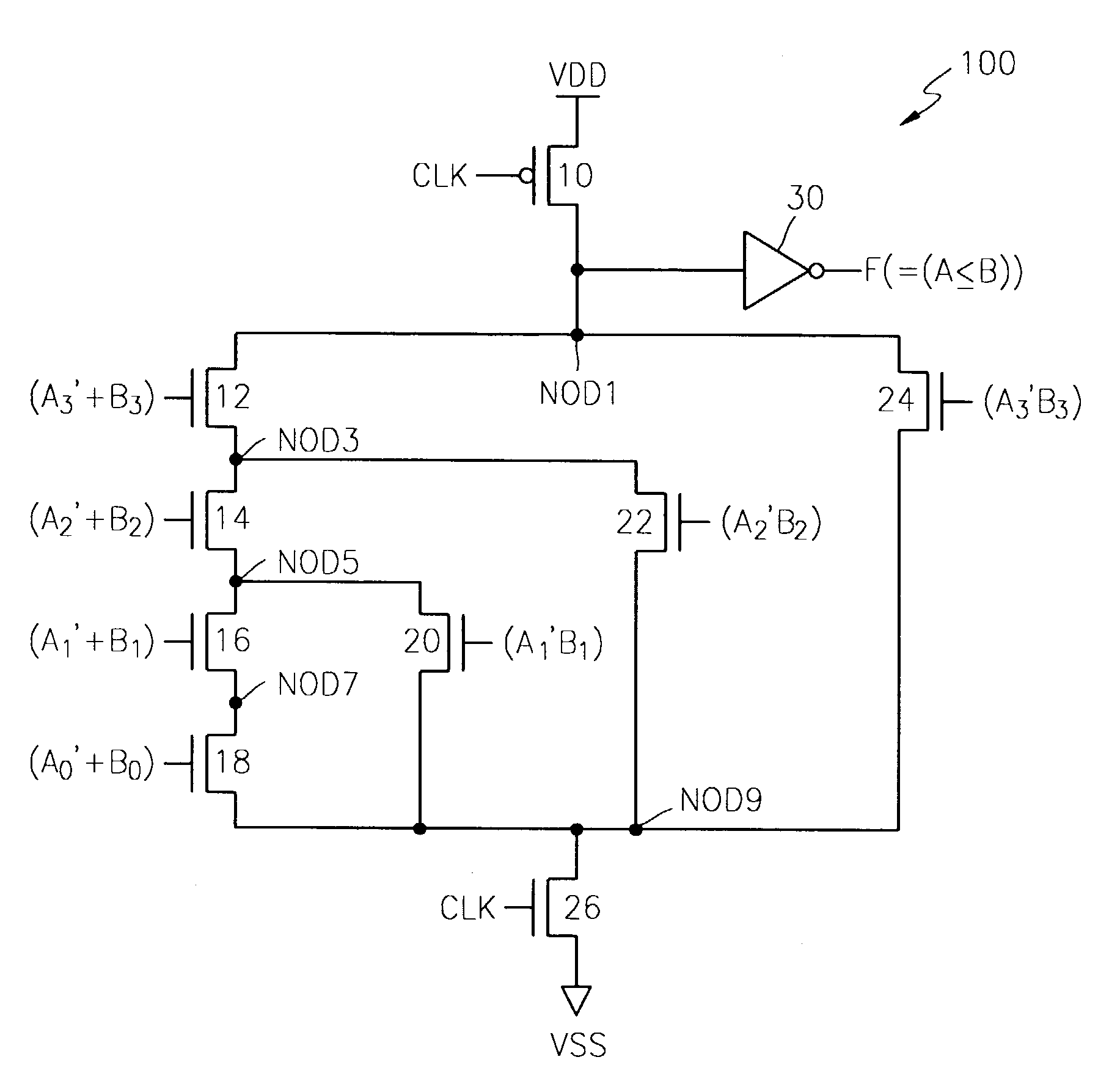
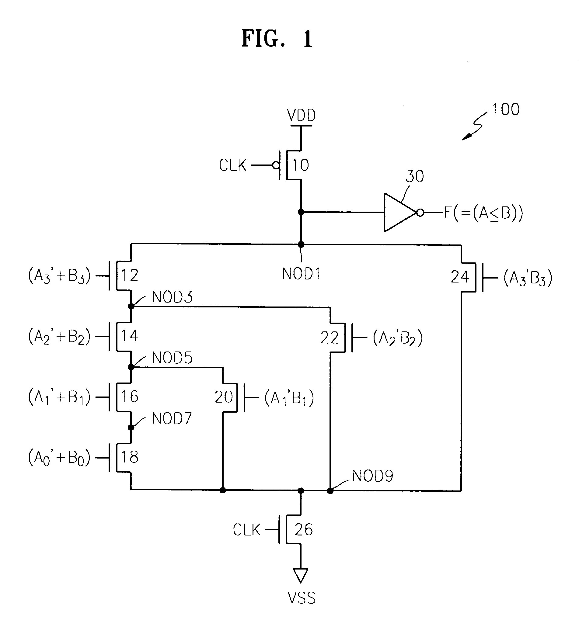
[0027]FIG. 1 illustrates a comparator circuit according to an exemplary embodiment of the present invention. Referring to FIG. 1, a comparator circuit 100 according to an exemplary embodiment of the present invention receives two binary data, i.e., a first binary data A[3:0]=A3A2A1A0 and a second binary data B[3:0]=B3B2B1B0, and outputs a comparison result by using Equations 1 and 2 below. It should be noted the binary comparator circuit according to exemplary embodiments of the present invention can be applied to a variety of data formats, sizes, bases, and numb...


PUM


Abstract

A binary comparator circuit and a binary data comparison method for reducing a layout area and power consumption and / or increasing comparison speed. The binary data comparison circuit and method receive all N bits of each of a first binary data An−1An−2 . . . A1A0 and a second binary data Bn−1Bn−2 . . . B1B0, and compare the first binary data and the second binary data to determine which of the first binary data and the second binary data is larger according to the following equation:F(A≦B)=A(n−1)′·B(n−1)+(A(n−1)′+B(n−1))·{A(n−2)′·B(n−2)+(A(n−2)′+B(n−2)) . . . {A1′·B1+(A1′+B1)·(A0′+B0)}}where subscripts denote a position of a bit of the N-bit binary data and a prime (′) indicates that a bit is inverted, and outputting a signal corresponding to the comparison result.

Description

CROSS-REFERENCE TO RELATED APPLICATIONS[0001]This nonprovisional patent application claims priority under 35 U.S.C. § 119, of Korean Patent Application No. 2002-50533, the entire contents of which are hereby incorporated by reference.BACKGROUND OF THE INVENTION[0002]1. Field of the Invention[0003]The present invention relates to a comparator circuit, and more particularly, to a comparator circuit implemented in a memory chip.[0004]2. Description of the Related Art[0005]In general, a binary comparator circuit is used for receiving two binary numbers or streams (also referred to as “data”) and determining which is larger. The simplest form of a binary comparator circuit employs a method of receiving two binary numbers or streams to be compared, comparing the received two binary numbers or streams sequentially from MSB (Most Significant Bit) to LSB (Least Significant Bit), and determining whether one of the two binary numbers or streams is larger than the other based on the result of t...

Claims


Application Information

Patent Timeline
Patent Type & Authority Patents(United States)
IPC IPC(8): G06F7/02
CPCG06F7/026G06F7/02
Inventor SHIN, JI-SUNLEE, JAE-JINHONG, YOU-PYO
Owner SAMSUNG ELECTRONICS CO LTD
Why Eureka
Try Eureka