Combined power main engine start system

a technology of engine start system and power main, which is applied in the direction of engine starter, machine/engine, engine/propulsion engine ignition, etc., can solve the problems of reducing the payload, heaviest, more expensive and less efficient, etc., and achieve the effect of maximising the power delivered

Active Publication Date: 2006-09-12
HAMILTON SUNDSTRAND CORP
View PDF18 Cites 52 Cited by
  • Summary
  • Abstract
  • Description
  • Claims
  • Application Information

AI Technical Summary

Problems solved by technology

The APU is thus oversized for the ECS mode and it is heavier, more costly and less efficient than if it were sized to match the ECS load alone.
The excess APU weight therefore shortens the range of the aircraft or reduces its payload.

Method used


Image

  • Combined power main engine start system
  • Combined power main engine start system

Examples


Embodiment Construction

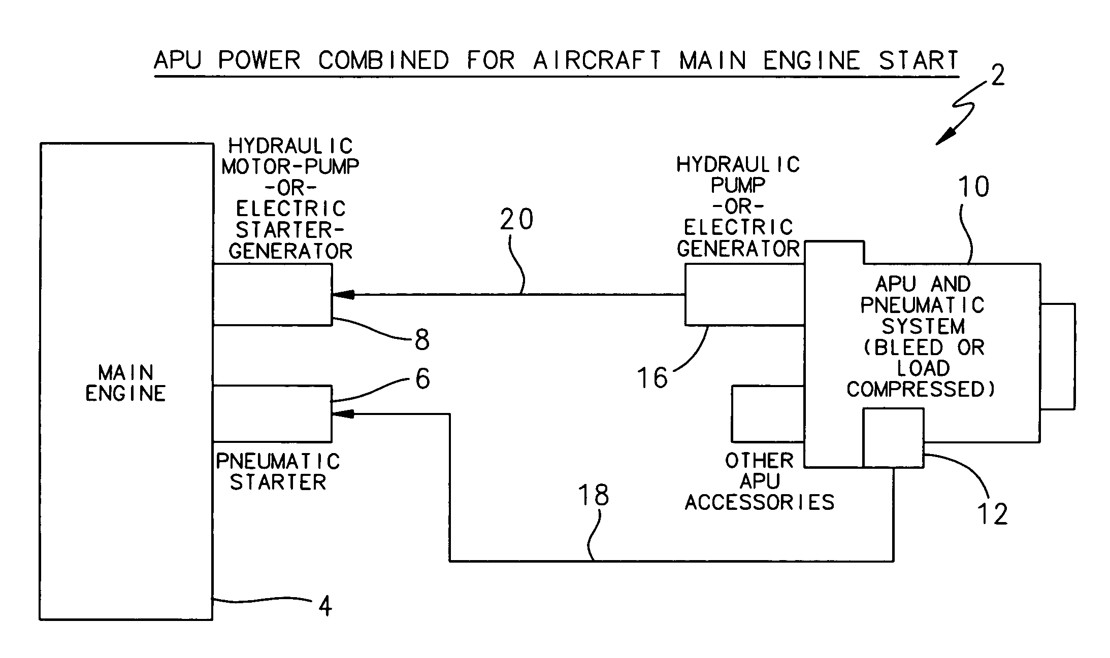
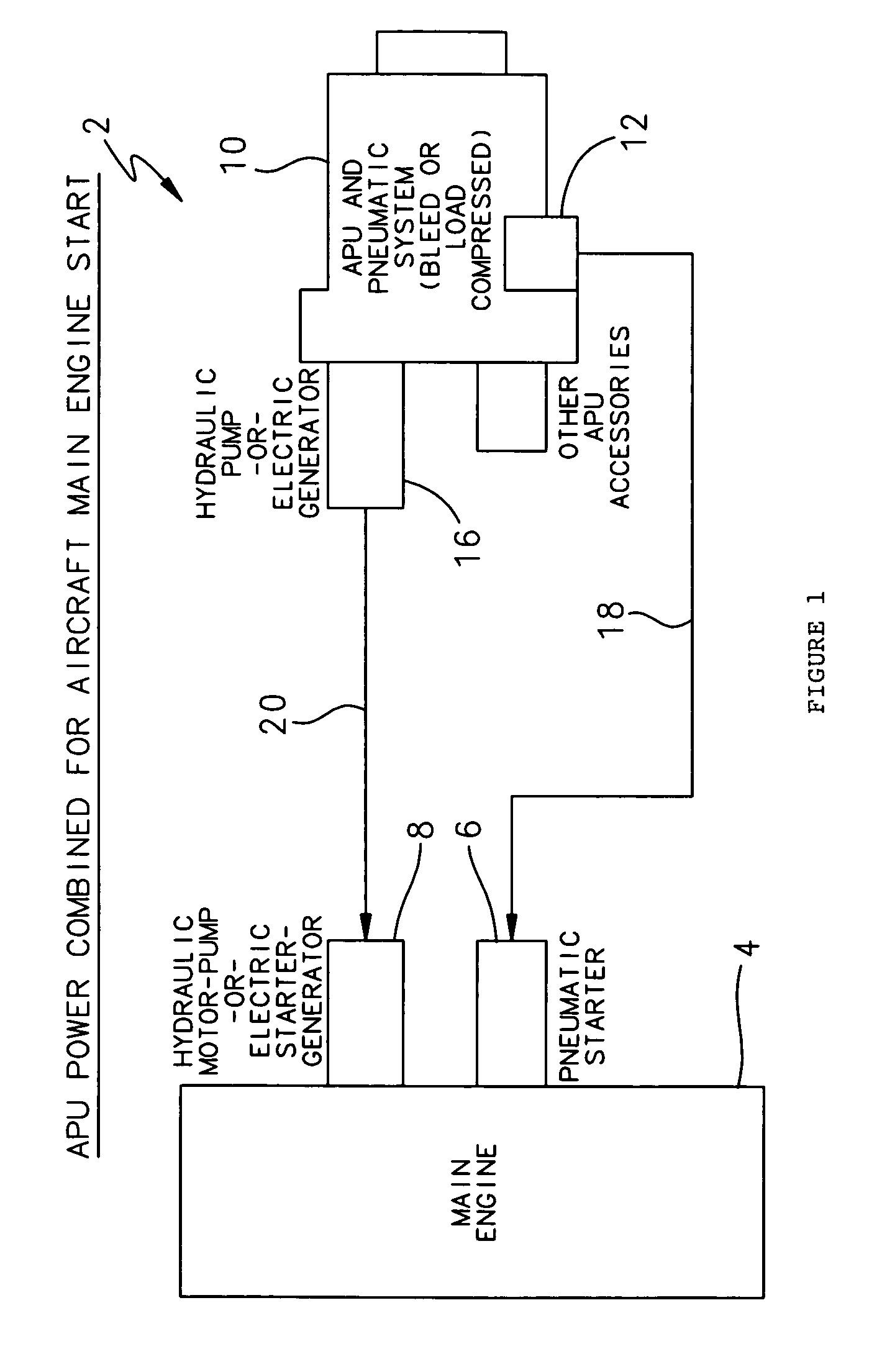
[0008]FIG. 1 is a block diagram of a combined power main engine start system 2 for aircraft according to the invention. A gas turbine propulsion engine 4 for an aircraft has an associated pneumatic starter 6 and an auxiliary starter 8. The pneumatic starter 6 is typically a pneumatic motor. The auxiliary starter 8 may be a dynamoelectric machine, such as an electric motor or starter / generator, a hydraulic motor or motor / pump, or a combination of such electric and hydraulic devices.

[0009]An auxiliary pump unit (APU) 10 aboard the aircraft has a pneumatic supply source 12. The pneumatic supply source 12 typically comprises a load compressor or powerhead bleed air source that is part of the APU 10. The APU 10 also has an auxiliary supply source 16 that supplies auxiliary power. The auxiliary supply source 16 may comprise a dynamoelectric machine, such as an electric generator or starter / generator, a hydraulic pump or motor / pump, or a combination of such electric and hydraulic devices. ...


PUM


Abstract

A starting system for starting the propulsion engines of gas turbine powered aircraft that combines power sources delivered by the APU so that essentially then entire power delivered by the APU for pneumatic, hydraulic and electric power is applied to corresponding starters on each propulsion engine during MES simultaneously.

Description

FIELD OF THE INVENTION[0001]The invention relates to engine starting systems for aircraft, and more particularly to engine starting systems for starting gas turbine propulsion engines aboard aircraft.BACKGROUND OF THE INVENTION[0002]Modern aircraft secondary power systems are becoming large with increasing demands for electric power and large power for starting the prime propulsion engines. These aircraft have a gas turbine powered auxiliary power unit (APU) on board to provide electrical, hydraulic and pneumatic power for operating systems aboard the aircraft when the propulsion engines are shut down as well as to provide power for starting the propulsion engines. Typically, pneumatic power, provided by a load compressor within the APU, has been used to start the propulsion engines. The load compressor has also been used to provide compressed air for the environmental control system (ECS) aboard the aircraft before and after the propulsion engines are started.[0003]The main engine ...

Claims


Application Information

Patent Timeline
Patent Type & Authority Patents(United States)
IPC IPC(8): F02C7/26
CPCF02C7/277F05D2220/50
Inventor THOMPSON, ROBERT G.
Owner HAMILTON SUNDSTRAND CORP
Why Eureka
Try Eureka