Method and apparatus for smokeless pyrotechnic display

a pyrotechnic display and smokeless technology, applied in the direction of aerial display rockets, fireworks, weapons, etc., can solve the problems of troublesome pyrotechnic display devices, building interiors, black powder propellant producing a large volume of smoke during combustion, etc., to facilitate rapid and uniform ignition of solid pyrotechnic compositions

Inactive Publication Date: 2006-09-12
WALKER RONALD R +1
View PDF5 Cites 17 Cited by
  • Summary
  • Abstract
  • Description
  • Claims
  • Application Information

AI Technical Summary

Benefits of technology

[0008]Briefly stated, a first embodiment the present invention provides a pyrotechnic display device configured to ignite solid pyrotechnic compositions within a launch tube prior to propelling them on a desired arc. A propelling charge of nitrocellulose is disposed within the launch tube below the solid pyrotechnic compositions, and separated therefrom by a gas-sealing disk. The an upper surface of the gas-sealing disk, adjacent the solid pyrotechnic compositions is optionally coated with a pyrotec

Problems solved by technology

It is known however, that black powder propellant produces a large volume of smoke during combustion.
This is particularly troublesome for pyrotechnic display devices intended for use within a building interior, such as an enclosed arena or stadium, or for use outside if the pyrotechnic display devices or aerial shells are discharged in close proximity to spectators, exhibitors, or other activities which would be obscured or impeded by the significant smoke produced during combustion.
However, the use of nitrocellulose in entertainment pyrotechnic display d

Method used


Image

  • Method and apparatus for smokeless pyrotechnic display
  • Method and apparatus for smokeless pyrotechnic display
  • Method and apparatus for smokeless pyrotechnic display

Examples


first embodiment

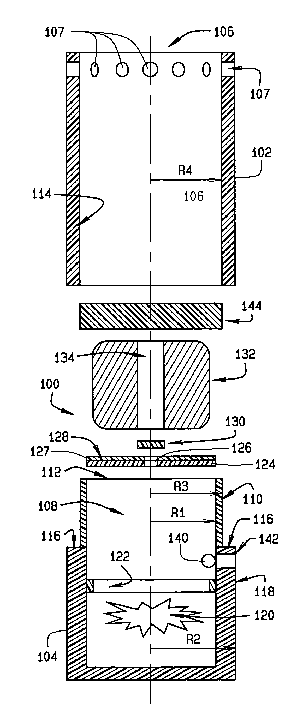
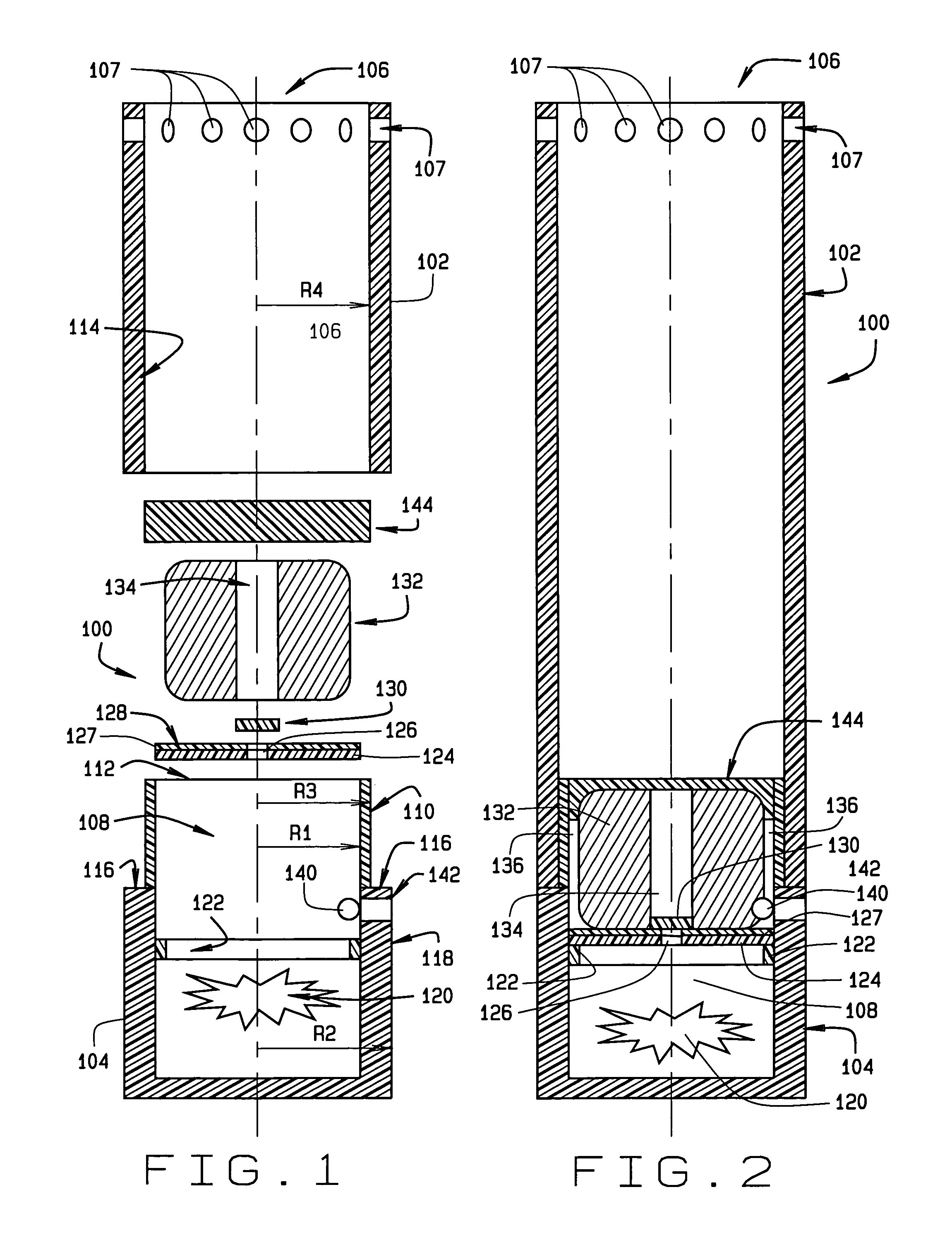
[0024]Turning to FIG. 1 and FIG. 2, the pyrotechnic display device 100 of the present invention is illustrated. The pyrotechnic display device 100 consists of a launch tube or barrel 102 having a generally cylindrical configuration and an enclosed base 104 The launch tube or barrel 102 preferably formed from spiral wound paper having an open discharge end 106, but may consist of any of a wide variety of materials having sufficient strength to maintain a shape during ignition and combustion of the pyrotechnic display device 100. Optional radial gas vents 107 may be disposed adjacent the open discharge end 106. The enclosed base 104 is preferably formed from a molded plastic, defining a open-ended combustion chamber 108, and is configured for attachment to the launch tube or barrel 102, opposite the open discharge end 106.

[0025]As illustrated in FIGS. 1 and 2, the enclosed base 104 is generally cylindrical, having a uniform inner radial dimension R1, and a uniform outer radial dimensi...

second embodiment

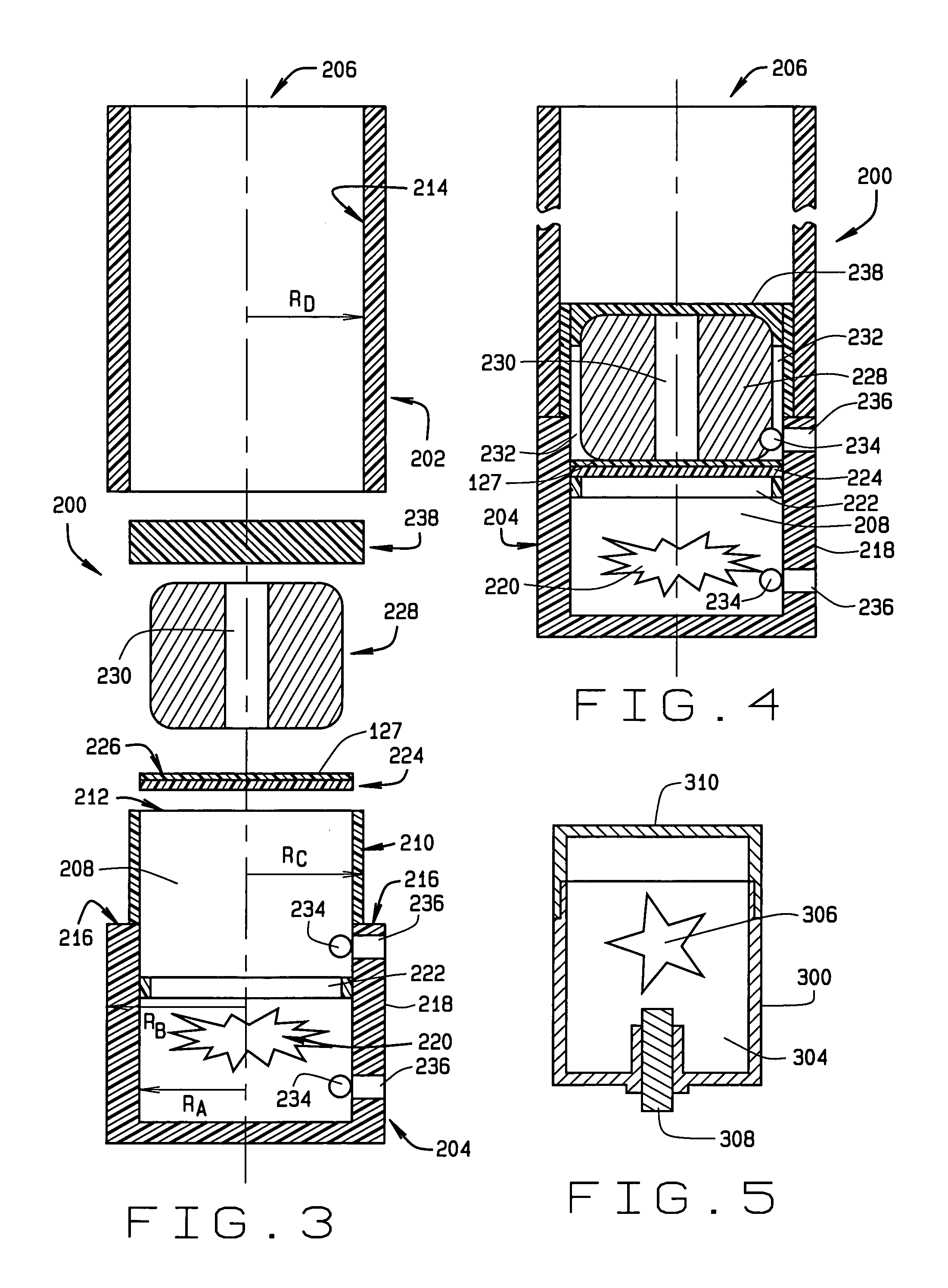
[0035]Turning to FIG. 3 and FIG. 4, the pyrotechnic display device 200 of the present invention is illustrated. The pyrotechnic display device 200 consists of a launch tube or barrel 202 having a generally cylindrical configuration and an enclosed base 204. The launch tube or barrel 202 preferably formed from spiral wound paper having an open discharge end 206, but may consist of any of a wide variety of materials having sufficient strength to maintain a shape during ignition and combustion of the pyrotechnic display device 200. The enclosed base 204 is preferably formed from a molded plastic, defining a open-ended combustion chamber 208, and is configured for attachment to the launch tube or barrel 202, opposite the open discharge end 206.

[0036]As illustrated in FIGS. 3 and 4, the enclosed base 204 is generally cylindrical, having a uniform inner radial dimension RA, and a uniform outer radial dimension RB. An annular recessed region 210 is provided adjacent an open end 212 of the ...


PUM


Abstract

A pyrotechnic display device configured to ignite solid pyrotechnic compositions or aerial shells within a launch tube prior to propelling them on a desired arc. A smokeless pyrotechnic propelling charge is disposed within the launch tube below the solid pyrotechnic compositions, and separated therefrom. An ignition source is disposed in operative relationship to the pyrotechnic compositions or aerial shells, which are ignited prior to ignition of the smokeless pyrotechnic propelling charge.

Description

CROSS-REFERENCE TO RELATED APPLICATIONS[0001]The present application is related to, and claims priority from, U.S. Provisional Patent Application Ser. No. 60 / 448,304 filed on Feb. 19, 2003.STATEMENT REGARDING FEDERALLY SPONSORED RESEARCH[0002]Not Applicable.BACKGROUND OF THE INVENTION[0003]The present invention relates generally to pyrotechnic display devices commonly referred to as fireworks, and in particular, to a pyrotechnic display device configured to produce an aerial shell, comet, or mine which, when ignited, smokelessly expels either non-burning body containing a burst charge and stars, or a solid pyrotechnic color or effect, to generate a reduced smoke aerial display, comet display, or star display.[0004]Traditionally, black power is used in the majority of pyrotechnic display devices for igniting and propelling solid pyrotechnic compositions such as star or comet displays from a launch tube. Black powder offer the advantages of rapid and hot combustion, thereby propelling...

Claims


Application Information

Patent Timeline
IPC IPC(8): F42B4/22F41F1/06F42B4/00F42B4/26
CPCF41F1/06F42B4/26F42B4/00
Inventor WALKER, RONALD R.NICKEL, RUSSELL R.
Owner WALKER RONALD R
Why Eureka
Try Eureka