Low disturbance deep tillage point

a deep tillage point and low surface disturbance technology, applied in drags, agriculture gas emission reduction, agricultural tools and machines, etc., can solve the problems of limiting the life of the point, the thin hardware attaching the surface or wall at the rear of the point is the limiting factor in the attempt to extend the point, and the rear of the point is prone to surface disturbance, etc., to achieve low surface disturbance and high fracture. , the effect of high residue ripping

Inactive Publication Date: 2006-09-12
DEERE & CO
View PDF31 Cites 23 Cited by
  • Summary
  • Abstract
  • Description
  • Claims
  • Application Information

AI Technical Summary

Benefits of technology

[0006]Deep tillage ripper point structure includes a nose designed for interaction between the wear shin and ripper point wings to provide high fracture and high residue ripping with low surface disturbance. Spring-loaded smooth coulters placed directly in front of the ripper shanks prevent hair-pinning of residue around shanks and place a vertical fracture plane in the soil profile directly in front of the shank. The ripper point and shank pass through the slot formed by the coulter to provide a fractured, minimally disturbed surface profile.
[0008]As lifted soil flows beside the shank, gently sloping forwardly and laterally extending ripper point wings fracture the soil a second time. The leading edges of the ripper wings angle rearwardly at about 45 degrees and are located below the top ripping plane of the ripper point. The wings therefore gradually enter the fracture plane left below the lifted compaction layer and initiate a second fracture of the soil profile. The wings are also designed to run in the fracture plane to provide for a low draft entry of the wings under the compaction layer.
[0009]The relationship of the wings to the point and the rear of the shank provide substantial advantage over most conventional point structures. The wings are spaced far enough rearward from the point so that the point and wear shin have enough time to lift, fracture, and part the soil profile in contact with the shank prior to any wing action. After the parting action of the soil profile is completed, the upward lift momentum of the soil is reduced as it flows around the shank. The soil lift begins to drop or level out and simultaneously the second lift of the soil profile is initiated. By waiting for the point-initiated upward momentum of the soil profile to decrease, wider and more aggressive wings can be utilized. For example, point structures with wings having widths greater than 9 to 12 inches and lift angles of approximately 15 to 25 degrees maximize the full-width fracture of the profile without compromising low soil surface disturbance and high surface residue. Wing downward slope in the outward direction can be in the range of approximately 0 to 15 degrees to provide the desired fracture action without unwanted surface disturbance.
[0010]In an embodiment wherein the wings are located more rearwardly relative to the standard compared to many previously available point structures, soil lifted by the wings falls behind the standard as well as beside the standard to help provide a level and undisturbed soil profile and close the ripper slot. The need for leveling and / or slot closing wheels is reduced compared to many of the current ripper points having wings in a more forward position relative to the shank. Lifted soil falling from the back edges of the wings can drop directly into the slot so that soil flow aggressiveness around the rear of the shank is reduced to help minimize surface disturbance and reduce wear at the back of the shank.
[0011]The shank-attaching structure of the point includes a large countersunk slot or oval cavity receiving a flange mounting bolt. The oval cavity allows the bolt head and nut to be recessed into the casting to prevent wear on the hex surfaces. The slot is large enough to provide access for a socket, or an open-ended wrench placed at an angle. To provide room for the countersunk slots, the rear walls of the ripper points are made thicker compared to most conventional point constructions with the wall thickness being on the order of half an inch or more. The thickened walls of the attaching structure not only protect the mounting hardware but also permit use of a higher wear material such as carbidic austempered ductile iron without increased risk of breakage from brittleness. The bolt does not bear the working load of the ripper point but simply keeps the point on while the ripper is in a non-working position or the standard is resetting.
[0012]A wingless point is also provided which generally has the design characteristics of the winged version except for the wings and rear shank mounting material. The wingless point weighs substantially less than the winged version and will provides an excellent lower cost, low disturbance ripper point.

Problems solved by technology

Conservation farmers desire a relatively wide point for fracturing but still want low surface disturbance and high residue retention, particularly when operating in highly erodible land conditions.
Soil flow beside the shank creates a substantial amount of wear on the rear of the shank as the soil tries to drop back towards the ripper slot.
Also, surface disturbance is created by soil flowing aggressively around the back edge of the ripper shank towards the ripper slot.
In many point structures, the thin hardware attaching surfaces or walls at the rear of the point are the limiting factor in attempts to extend point life.
The carbides used to extend the wear life often deposit in the thin section around the attaching bolt slot and result in brittleness and part breakage.
Therefore, the thin walls were the limiting factor in the amount of carbides that could be used without risk of cracking.

Method used


Image

  • Low disturbance deep tillage point
  • Low disturbance deep tillage point
  • Low disturbance deep tillage point

Examples


Embodiment Construction

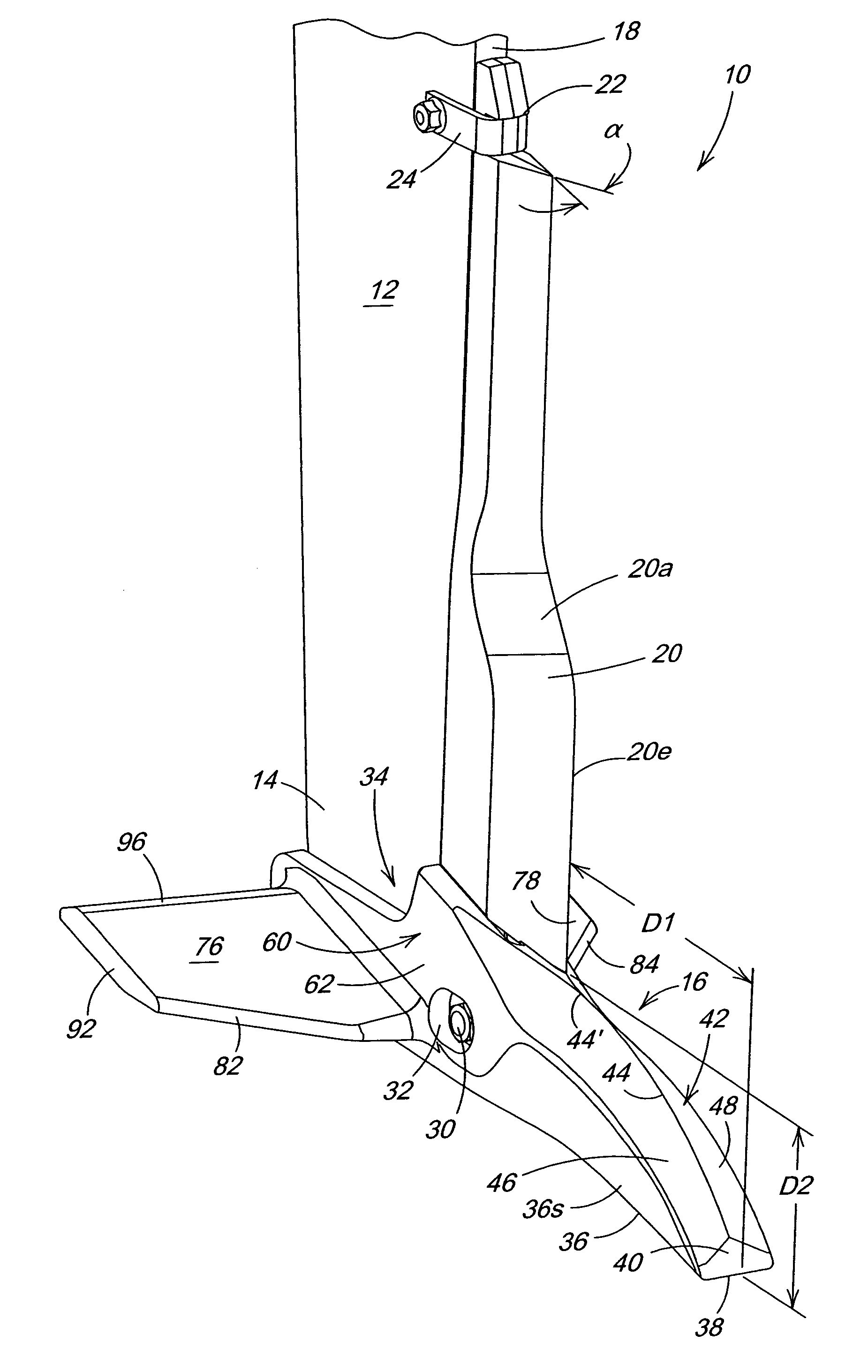
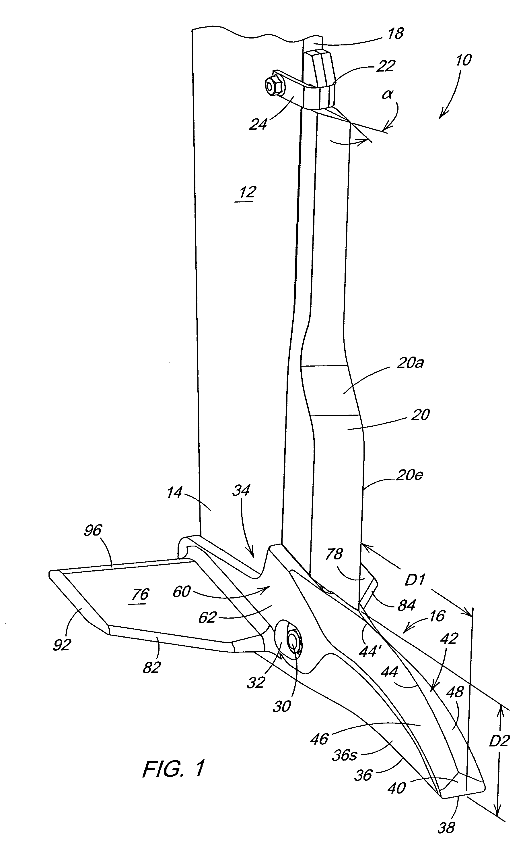
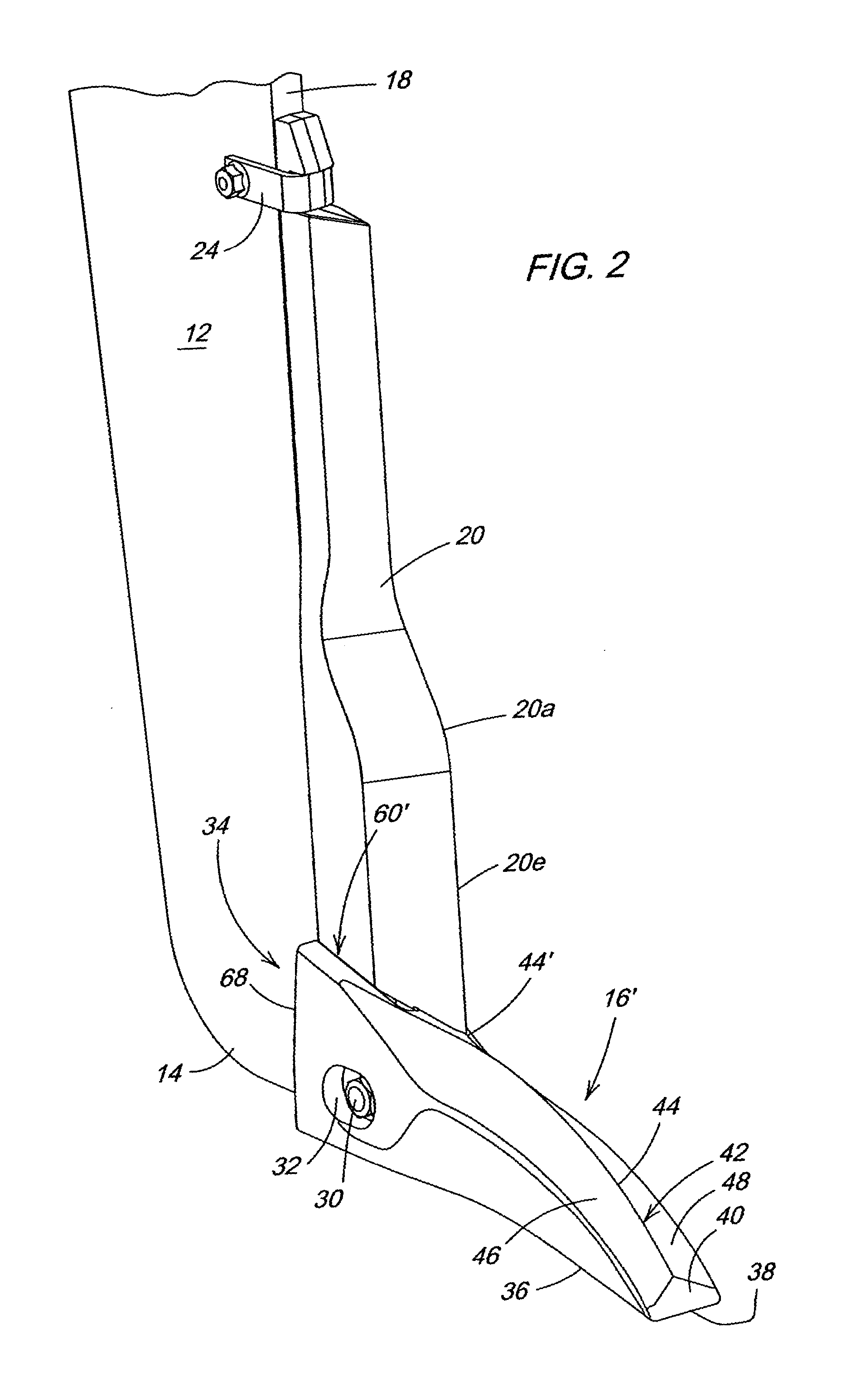
[0020]Referring to FIG. 1, therein is shown a ripper standard assembly 10 including an upright narrow standard or shank 12 having an upper end adapted for support by a ripper frame (not shown) and a lower mounting end 14 receiving a ripper point 16. The standard 12 had a leading edge or surface 18 which supports a parting fin or wear shin 20 having a back surface abutting the surface 18 of the shin 20. An upper notched end 22 is fixed to the shank 12 by a bolted bracket 24, and the lower end of the shin 20 is received by the point 16. The point 16 is slid onto the lower end 14 and a bolt 30 is inserted through a hole in the shank 12 and a set of slots 32 in the point to retain the point during transport and tripping of the standard. Ground reaction forces are transferred directly from the point 16 to the end 14 so that the bolt 30 is not heavily loaded during tillage operations.

[0021]The point 16 has a main body 34 with nose 36 having a horizontal front edge 38 and forward face 40 a...


PUM


Abstract

Ripper point structure includes a nose with a tapered top that initiates lift and fracture of compacted soil layers. The tapered top with an included angle of about 100 degrees just forward of the parting wear shin creates a parting stress which increases until the center portion of the soil profile is cut by a sharp leading edge of the shin. In a winged embodiment, gently sloping ripper point wings gradually enter the fracture plane left below the lifted compaction layer and initiate a second fracture of the soil profile. The wings are spaced rearwardly from the point so that the point and wear shin have enough time to lift, fracture, and part the soil profile in contact with the shank prior to any wing action.

Description

FIELD OF THE INVENTION[0001]The present invention relates generally to agricultural tillage equipment and, more specifically, to deep tillage points providing low surface disturbance.BACKGROUND OF THE INVENTION[0002]Deep tillage points such as shown in U.S. Pat. Nos. 5,437,337 and 5,540,288 have been designed to leave soil surface relatively level while still achieving substantial sub-soil fracturing. In commonly assigned U.S. Pat. No. 6,443,237 a central body or point with opposed wings extend downwardly and laterally is shown. The upper surface of each of the wings forms an upward angle in the rearward direction of approximately 15 degrees with the horizontal. The point is slid onto a lower mounting portion of a ripper shank, and a bolt is inserted through a hole in the shank and a set of slots in the lower rear portion of the point. The bolt, hole, and slot arrangement provides a loose connection between the shank and the point and functions primarily to retain the point when the...

Claims


Application Information

Patent Timeline
Patent Type & Authority Patents(United States)
IPC IPC(8): A01B39/20A01B15/02
CPCA01B15/025Y02P60/20
Inventor STEINLAGE, DAVID LEEFLEICHMANN, ARON WESLEYBEECK, MARK DONALDMYERS, BRIAN E.
Owner DEERE & CO
Why Eureka
Try Eureka