Portable spray fan

a portable, fan technology, applied in the direction of spray nozzles, movable spraying devices, liquid spraying devices, etc., can solve the problems of not being suitable for wearing around the user's neck as a necklace, not being able to accurately direct the airflow, and being unsuitable for walking outside. , to achieve the effect of accurate directing the airflow, and reducing the risk of injury

Inactive Publication Date: 2006-09-12
VECTACOR A DIV OF BONIS
View PDF14 Cites 24 Cited by
  • Summary
  • Abstract
  • Description
  • Claims
  • Application Information

AI Technical Summary

Benefits of technology

[0007]Such a fan has the advantage that the fan blades or hub does not obstruct the spray. Also, with the arrangement of the inventive device, the spray is directed into the air stream or airflow so that the spray is efficiently carried by the airflow.
[0008]The avoidance of a shroud or grill means that the airflow is uninterrupted, and the fan is therefore much more efficient.
[0009]In one embodiment, the fan may include a cord so that the fan can be worn around a user's neck and be stably mounted on the wearer's chest. As a result the wearer can accurately direct the airflow onto a specific location, such as his or her face.

Problems solved by technology

For example, in fair grounds, theme parks, and the like, which are generally located in warm climates, a person strolling outside can find it unpleasantly hot, especially if the sun is beating down on gravel or hot tarmac.
The problem with such an arrangement is that the rotating fan vanes interrupt the spray, causing water to be scattered out of the airflow.
This arrangement, while portable, is not suitable for wearing around the user's neck as a necklace.
The problem with such an arrangement is the device must be manually positioned so that the airflow and spray are directed toward the user's face.
This device can not be mounted in a stable position against the user so that the air and spray flow are directed toward the user's face.
Also, the shroud interrupts the airflow and thus reduces efficiency, which is important in the case of battery-powered devices.

Method used


Image

  • Portable spray fan
  • Portable spray fan
  • Portable spray fan

Examples


Embodiment Construction

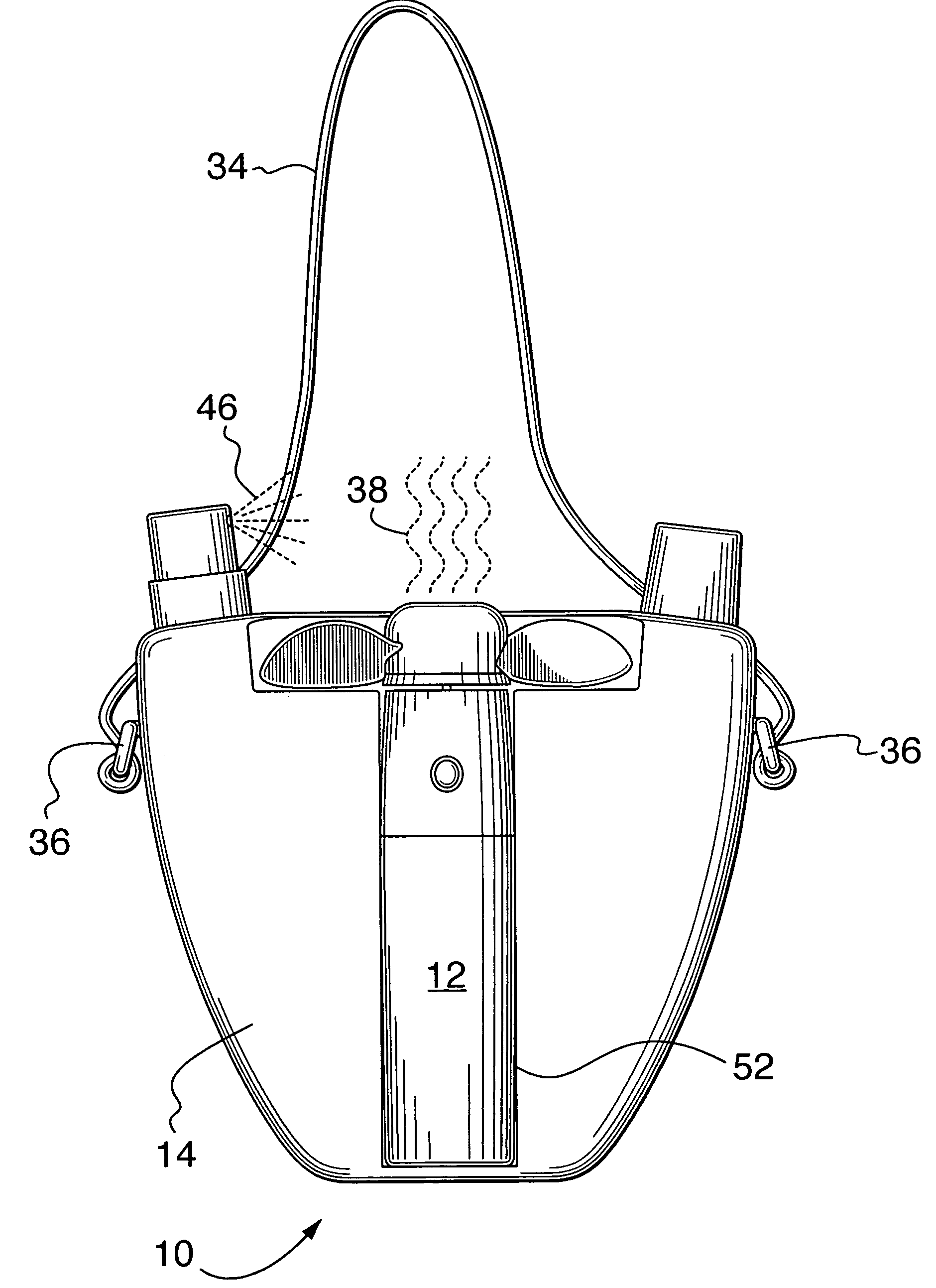
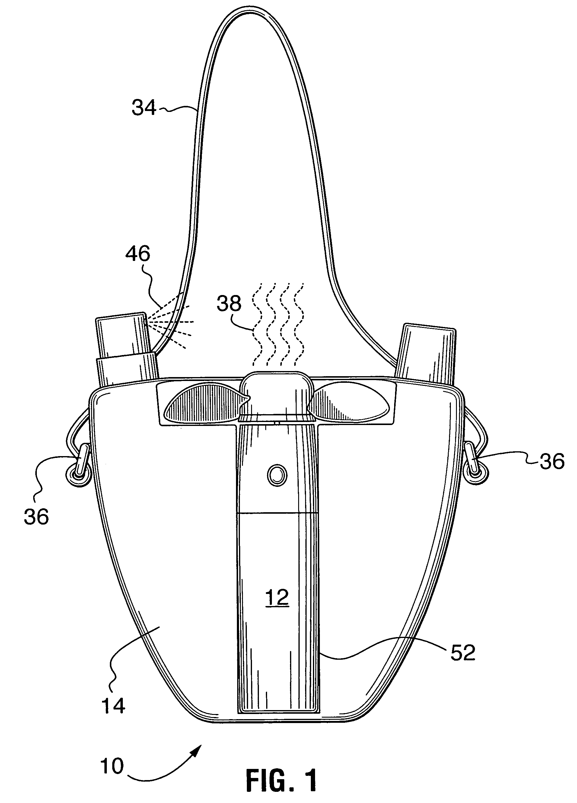
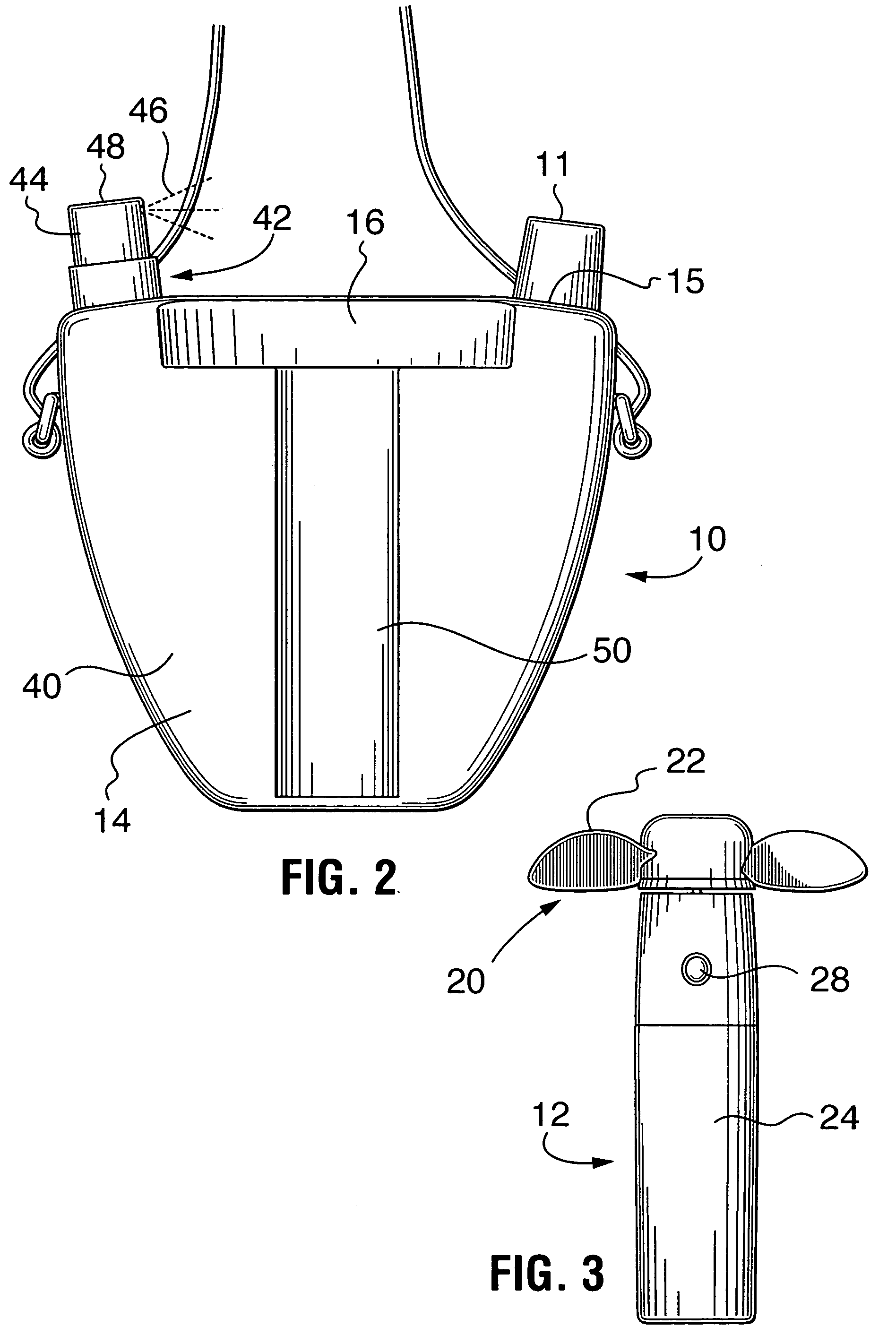
[0018]Referring to FIGS. 1 to 3, the portable spray fan 10 in accordance with the principles of the invention has a spray bottle body 14. The spray bottle body 14 may generally be in the shape of an inverted U constructed of a durable plastic. The spray bottle body 14 defines a water reservoir 40 having a delivery tube (not shown) therein. One end of the delivery tube is connected to a nozzle assembly 42. Nozzle 44 is directed to provide a spray of water 46 upstream of the air stream or airflow 38 produced by the impeller 20 (described below). The nozzle 44 is fastened to a push button knob 48 to allow water from the spray bottle body 14 to be expelled from the nozzle 44 when the knob 48 is activated by pushing down thereon. Alternatively, the actuator may be a pressure trigger type of actuator. A user has to loosen the knob 48 prior to putting water into the spray bottle body 14.

[0019]The spray bottle body 14 includes a mounting base portion 16. The opposite side of the spray bottl...


PUM


Abstract

Disclosed is a personal fan assembly comprising a spray bottle body for storing a liquid and having a nozzle for dispensing the liquid on demand in the form of a spray; and a fan unit releasably attachable to said spray bottle body. The fan unit includes an impeller to create an air stream, and the nozzle is located downstream of the impeller and to one side thereof out of the air stream. The nozzle is oriented at an angle to the air stream so as to direct the spray into the air stream at an angle. The spray bottle body may be in the shape of a U, with the opening in the horseshoe adapted to releasably receive the fan unit. Alternatively, the spray bottle body may be in the form of a water pitcher and the fan unit is mountable in a cylindrical housing within the spray bottle body.

Description

FIELD OF THE INVENTION[0001]This invention relates to the field of portable fans, and in particular to a personal spray fan.BACKGROUND OF THE INVENTION[0002]There are many situations where it is desirable for a person to be able to carry a portable fan for personal cooling as they move about. For example, in fair grounds, theme parks, and the like, which are generally located in warm climates, a person strolling outside can find it unpleasantly hot, especially if the sun is beating down on gravel or hot tarmac.[0003]U.S. Pat. No. 5,752,662 describes a personal spray fan. The device includes a spray body with a fan housing mounted over top. The spray nozzle is situated behind the fan hub and blades. The problem with such an arrangement is that the rotating fan vanes interrupt the spray, causing water to be scattered out of the airflow.[0004]U.S. Pat. No. 5,843,344 describes another personal spray fan. The device includes a fan body releasably secured to the front face of a misting de...

Claims


Application Information

Patent Timeline
Patent Type & Authority Patents(United States)
IPC IPC(8): A62C13/62A62C5/00B05B1/00B05B15/00B05B7/00B05B11/00
CPCB05B3/022B05B11/0005
Inventor STENGEL, ED
Owner VECTACOR A DIV OF BONIS
Why Eureka
Try Eureka