Vehicle occupant restraint system

a technology for occupants and seats, applied in the direction of pedestrian/occupant safety arrangements, chairs, tractors, etc., to achieve the effect of rapid deploymen

Inactive Publication Date: 2006-09-12
NHK SPRING CO LTD
View PDF19 Cites 23 Cited by
  • Summary
  • Abstract
  • Description
  • Claims
  • Application Information

AI Technical Summary

Benefits of technology

[0010]According to a preferred embodiment of the present invention, the crash sensor additionally comprises a simple crash sensor for detecting an actual occurrence of a vehicle crash, and the control unit is adapted to actuate the power actuator so as to raise the restraining member to the partly deployed position according to an output of the crash prediction sensor and to raise the restraining member to the fully deployed position according to an output of the simple crash sensor. Thus, when a crash is only predicted, the restraining member is deployed only partially so that the vehicle occupant is not excessively inconvenienced by the deployment of the restraining member. If an actual crash should occur after a crash has been predicted, because the restraining member is already partly deployed, the restraining member can reach the fully deployed position in a very short period of time after the occurrence of the actual crash.
[0011]According to a particularly preferred embodiment of the present invention, the restraining member comprises a laterally extending member located under the seat bottom at a substantially longitudinally middle point of the seat bottom, and a pair of arms pivotally supporting the laterally extending member with respect to a seat frame. Additionally, the power transmitting member comprises a threaded rod extending in a fore-and-aft direction and rotatably supported by a moveable member which is guided by the seat frame so as to be moveable in a fore-and-aft direction, and a nut fixedly attached to the seat frame and threadably engaging the threaded rod, the arms being pivotally supported by the movable member and being provided with an arcuate slot receiving a pin fixedly attached to the seat frame. Most preferably, the power actuator comprises an electric motor having an output shaft extending laterally under the seat bottom, and the moveable member comprises a gear box for transmitting a rotation of the output shaft to the threaded rod. This arrangement allows the vehicle occupant restraint system to be incorporated in a vehicle seat in a highly compact manner.
[0012]According to another embodiment of the present invention, the power transmitting member comprises a threaded rod and a nut threadably engaging the threaded rod, and the power actuator comprises an electric motor for turning one of the threaded rod and nut, the other of the threaded rod and nut being drivingly connected to the restraining member. Additionally, the threaded rod is connected to the restraining member, and the power actuator comprises a pyrotechnical actuator which is adapted to move the threaded rod in a direction to deploy the restraining member while the electric motor is adapted to turn the threaded rod, the nut comprising a split piece which is normally urged by a spring member against a slanted surface of a guide member in such a manner that the nut is normally placed in a threadable engagement with the threaded rod when the threaded rod is turned in a normal direction to move the restraining member toward the deployed position and is allowed to move freely with respect to the threaded rod when the threaded rod is actuated by the pyrotechnical actuator in the direction to deploy the restraining member. The pyrotechnical actuator ensures an extremely rapid deployment of the restraining member, and this arrangement allows the use of such a pyrotechnical actuator without compromising the benefit of the present invention. More specifically, the vehicle occupant restraint system implemented in this fashion can be used repeatedly simply by replacing the pyrotechnical actuator (if it has been actuated) without replacing the remaining part of the system.

Problems solved by technology

This is particularly significant when the crash sensor includes a crash prediction sensor because the prediction could be wrong and the restraining member may have to be deployed a number of times even when a vehicle crash has never occurred.

Method used


Image

  • Vehicle occupant restraint system
  • Vehicle occupant restraint system
  • Vehicle occupant restraint system

Examples


Embodiment Construction

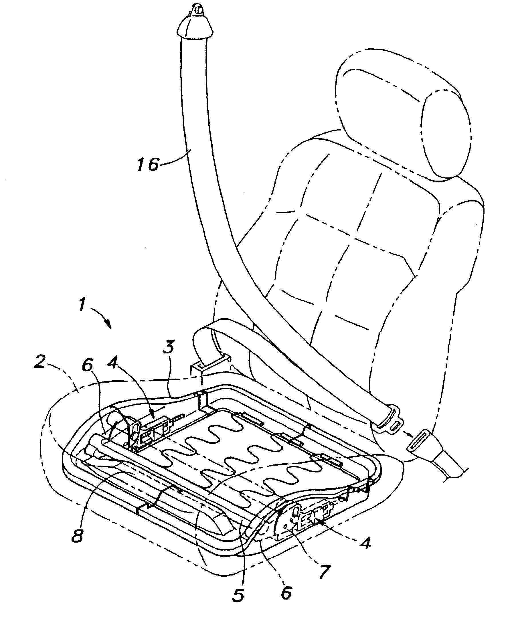
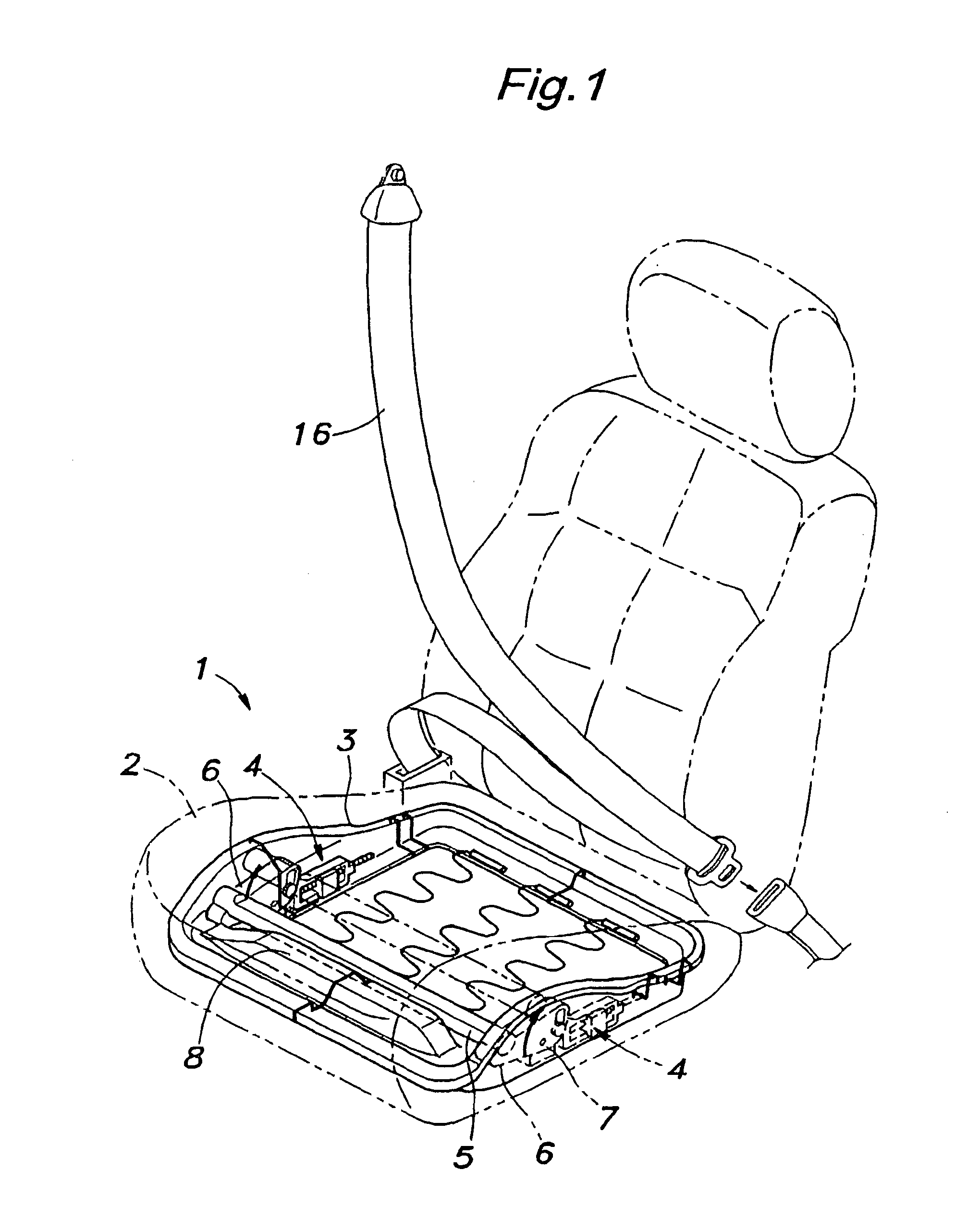
[0023]FIG. 1 is a perspective view of a vehicle seat 1 embodying the present invention. The seat 1 comprises a seat bottom 2 made of plastic foam, and a rectangular dish-shaped seat frame 3 for supporting the lower part of the scat bottom 2. A pair of power actuators 4 are attached to either side wall of the seat frame 3 and form a part of a vehicle occupant restraint system. A restraining pipe member 5 extends laterally under an intermediate part of the seat bottom 2, preferably only slightly ahead of the longitudinally middle point of the seat bottom 2.

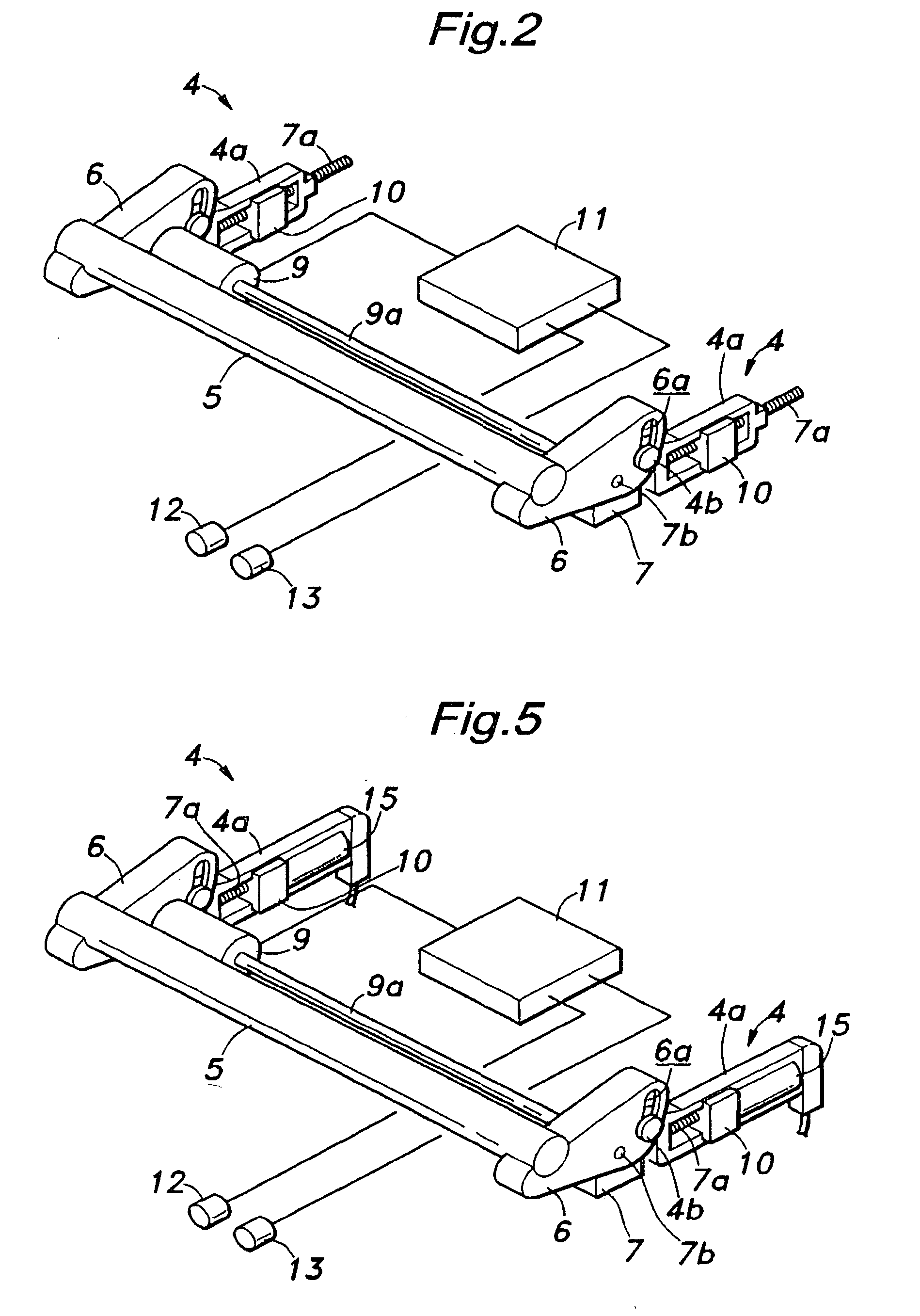
[0024]A pair of arm members 5 are attached to the corresponding ends of the restraining pipe member 5, respectively. As best shown in FIG. 2, an intermediate point of each arm member 6 is pivotally attached to a gear box 7 via a pivot shaft 7b. As will be described hereinafter, the gear boxes 7 are slidably attached to the seat frame 3 although it is not shown in the drawing. Thus, the restraining pipe member 5 can move vertically a...


PUM


Abstract

In a vehicle occupant restraint system for restraining a lower part of a vehicle occupant, an arrangement for moving a restraining member from a retracted position to a deployed position upon detection and/or prediction of a vehicle crash by a crash sensor is adapted in such a manner that the restraining member cannot be made to move from the deployed position to the retracted position by an external force applied to the restraining member but can be made to move from the retracted position to the deployed position and from the deployed position back to the retracted position by a force transmitted from a power actuator to the restraining member via a power transmitting member. Thus, while the restraining member is capable of withstanding the load of restraining the vehicle occupant, even when the restraining member is deployed, it can be brought back to the retracted position so that the restraining system can be used repeatedly. This is particularly significant when the crash sensor includes a crash prediction sensor because the prediction could be wrong and the restraining member may have to be deployed a number of times even when a vehicle crash has never occurred.

Description

TECHNICAL FIELD[0001]The present invention relates to a vehicle occupant restraint system which is adapted to be incorporated in a vehicle seat, and in particular to a vehicle occupant restraint system which can restrain a lower part of the vehicle occupant in combination with an existing vehicle occupant restraint system for restraining an upper part of the vehicle occupant in case of an impact situation such as a vehicle crash.BACKGROUND OF THE INVENTION[0002]Passenger vehicles are commonly equipped with restraint systems, typically in the form of seat belts, for restraining primarily an upper part of the vehicle occupant in case of a frontal crash. However, it is known that the vehicle occupant may submarine or slip forward under the seat belt at the time of a vehicle crash. This can occur if the seat belt fails to restrain the pelvic part of the vehicle occupant for various reasons, and severely impairs the capability of the scat belt to restrain the vehicle occupant. Also, it i...

Claims


Application Information

Patent Timeline
Patent Type & Authority Patents(United States)
IPC IPC(8): B60N2/42B60N2/427B60R21/02
CPCB60N2/4279B60N2/42763
Inventor MASUDA, KOTAKESHITA, TAKASHIMATSUNAGA, HIROSHI
Owner NHK SPRING CO LTD
Why Eureka
Try Eureka