Optical transceiver and method for producing the same

a transceiver and optical technology, applied in the field of optical transceivers, can solve the problems of increasing the cost of products, large proportion of manual operation in the production process,

Inactive Publication Date: 2006-09-12
SEIKO EPSON CORP
View PDF24 Cites 27 Cited by
  • Summary
  • Abstract
  • Description
  • Claims
  • Application Information

AI Technical Summary

Benefits of technology

[0052]It is desirable that the hardening resin be a light-transmissive resin that is either a photocurable resin or a thermosetting resin. It is convenie

Problems solved by technology

However, in the above method of producing such an optical transceiver, a complicated three-dimensional alignment must be carried out when assembl

Method used


Image

  • Optical transceiver and method for producing the same
  • Optical transceiver and method for producing the same
  • Optical transceiver and method for producing the same

Examples


Embodiment Construction

[0082]A description of exemplary embodiments of the present invention is provided below with reference to the drawings.

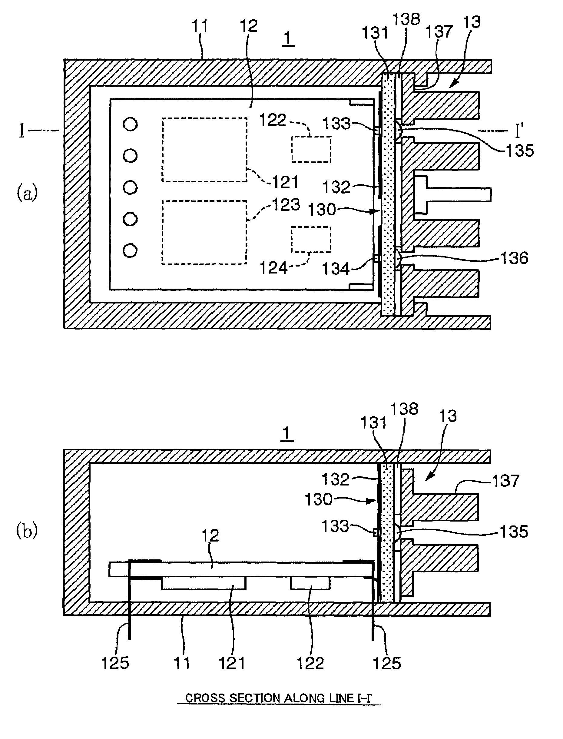
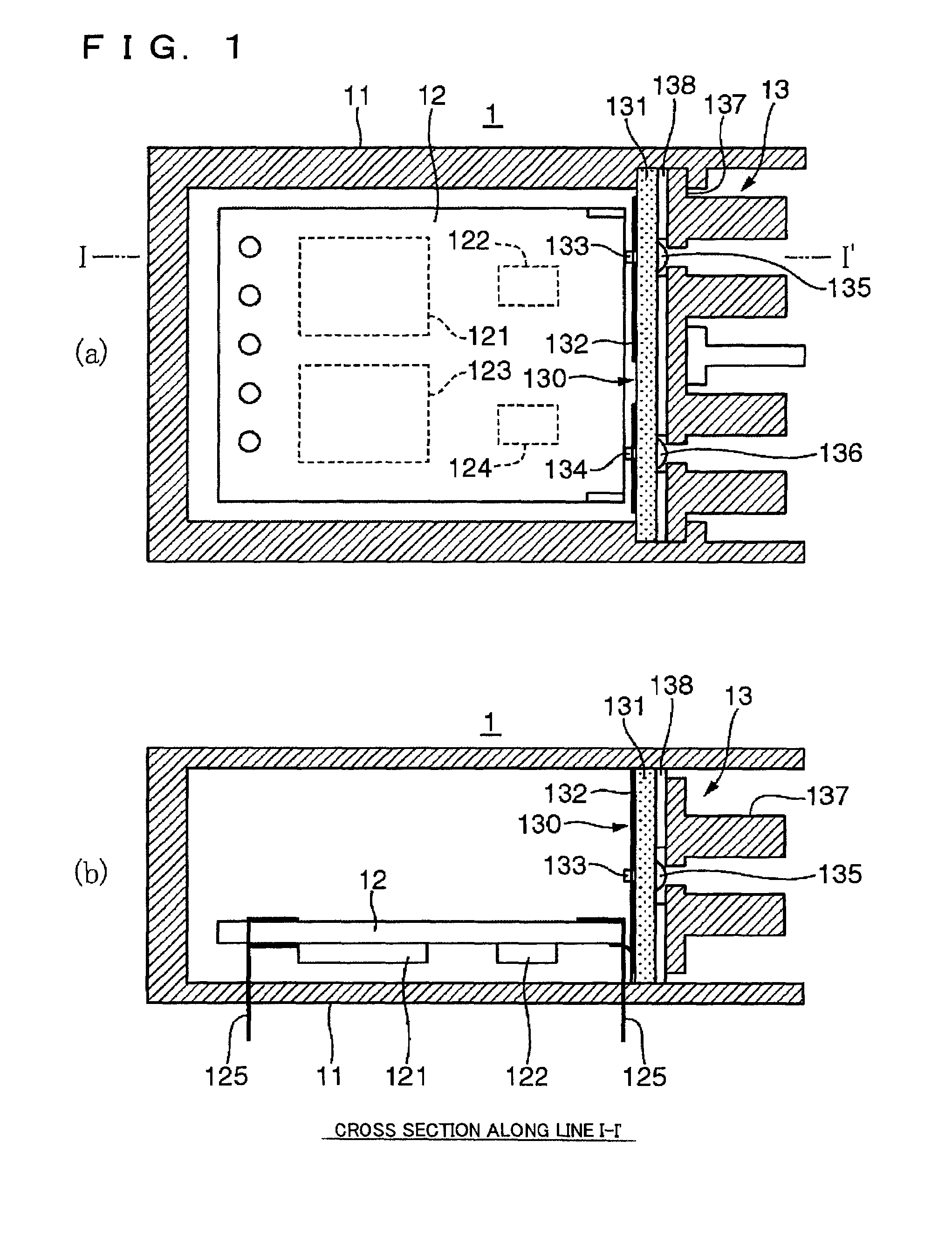
[0083]FIGS. 1(a) and 1(b) show a structure of an optical transceiver. FIG. 1(a) is a horizontal sectional view of the internal arrangement of an optical transceiver 1. FIG. 1(b) is a sectional view taken along plane I–I′ in FIG. 1(a).

[0084]As shown in FIGS. 1(a) and 1(b), a signal processing substrate 12 and an optical coupling unit 13 are disposed in a housing 11 of the optical transceiver 1. A parallel-serial signal converting circuit 121, a drive circuit 122, an amplifying circuit 124, a serial-parallel signal converting circuit 123, a lead frame 125, etc., are disposed on the signal processing substrate 12. The parallel-serial signal converting circuit 121 converts an externally supplied parallel signal into a serial signal. The drive circuit 122 changes the serial signal to a drive signal of a light emitter 133. The amplifying circuit 124 shapes a light signal ...


PUM


Abstract

The invention provides an optical transceiver which makes it possible to simplify a production process. An optical transceiver of the present invention includes an optical socket to mount an optical plug disposed at one end portion of an optical fiber); a light-condensing device; and an optical element to emit light in accordance with a supplied electrical signal and an optical element to generate an electrical signal in accordance with a received light signal; and a light-transmissive substrate to support the optical socket, the light-condensing device, and the optical elements so that the optical fiber, the light-condensing device, and the optical elements are aligned on an optical axis of the optical transceiver.

Description

BACKGROUND OF THE INVENTION[0001]1. Field of Invention[0002]The present invention relates to an optical transceiver used for transmission and / or reception using an optical fiber as a medium. The method also relates to a method of producing the same.[0003]2. Description of Related Art[0004]Optical fibers can be used in the related art in, for example, local area networks (LANs), direct connectors to mutually connect computers, connectors to mutually connect computers and digital audio / video devices, etc. In these devices, an optical transceiver is used. The optical transceiver converts an electrical signal to a light signal, transmits the light signal to an optical fiber, and converts the light signal received from the optical fiber back into an electrical signal. For example, the optical transceiver includes a socket, a ball lens, and an integrated circuit (IC) substrate. The socket receives a plug that is mounted to one end of the optical fiber. The ball lens is disposed between th...

Claims


Application Information

Patent Timeline
IPC IPC(8): G02B6/36G02B6/14G02B6/42H01L31/0232H01S5/022
CPCG02B6/4204G02B6/4214G02B6/4221G02B6/425G02B6/4246G02B6/4292G02B6/4227
Inventor NAGASAKA, KIMIOMIYAMAE, AKIRAKANEKO, TAKEOFUJII, EIICHIAMAKO, JUNIDE, TSUGIOKITAMURA, SHOJIRO
Owner SEIKO EPSON CORP
Why Eureka
Try Eureka