Rotationally immobilized dental implant and abutment system

a dental implant and abutment technology, applied in dental implants, dental surgery, medical science, etc., can solve the problems of angular misalignment of the artificial tooth about the axis, certain difficulties with the prior system, and the need for a sturdy foundation for dental crowns, so as to improve the arrangement of osseodontics.

Inactive Publication Date: 2006-09-12
RASSOLI JEFF
View PDF6 Cites 41 Cited by
  • Summary
  • Abstract
  • Description
  • Claims
  • Application Information

AI Technical Summary

Benefits of technology

[0011]The present invention involves a unique construction of dental implant and abutment members in an endosseous dental implant system that avoids the problems described with conventional dental implant systems. Specifically, the unique construction of the dental implant and abutment members according to the present invention provides a system that prevents rotation of the abutment member relative to the implant member, and which also ensures that the post of one of the mating abutment and implant members seats completely in the socket of the other member. As a consequence, the present invention provides an improved osseodontic arrangement for seating a dental abutment member relative to a dental implant member.

Problems solved by technology

However, dental crowns require a sturdy foundation.
However, in some instances, this is impractical since a tooth may be so badly damaged due to disease or injury that the entire tooth must be removed.
In early systems one difficulty that occurred was that the abutment member would twist relative to the implant member, thus creating angular misalignment of the artificial tooth about the axis of the fastening screw.
However, certain difficulties with this prior system occurred.
Specifically, due to the necessary dimensional tolerance that must exist for a post to be inserted into a socket, conventional implant and abutment systems of the type described still experience some slight twisting of the abutment member relative to the implant member.
While this arrangement did address the problem of rotation of the post relative to the socket, it creates another problem in that it is possible for an interstitial gap to exist between the faces of the gingival ends of the implant and socket members surrounding the socket opening and the post.

Method used


Image

  • Rotationally immobilized dental implant and abutment system
  • Rotationally immobilized dental implant and abutment system
  • Rotationally immobilized dental implant and abutment system

Examples


Embodiment Construction

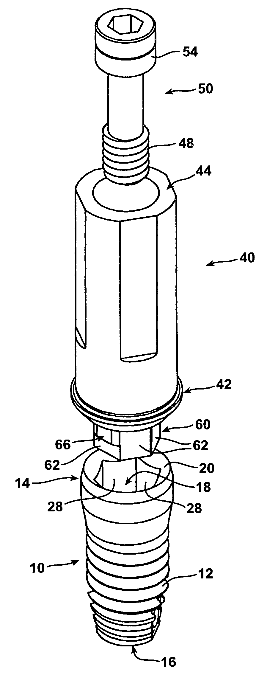
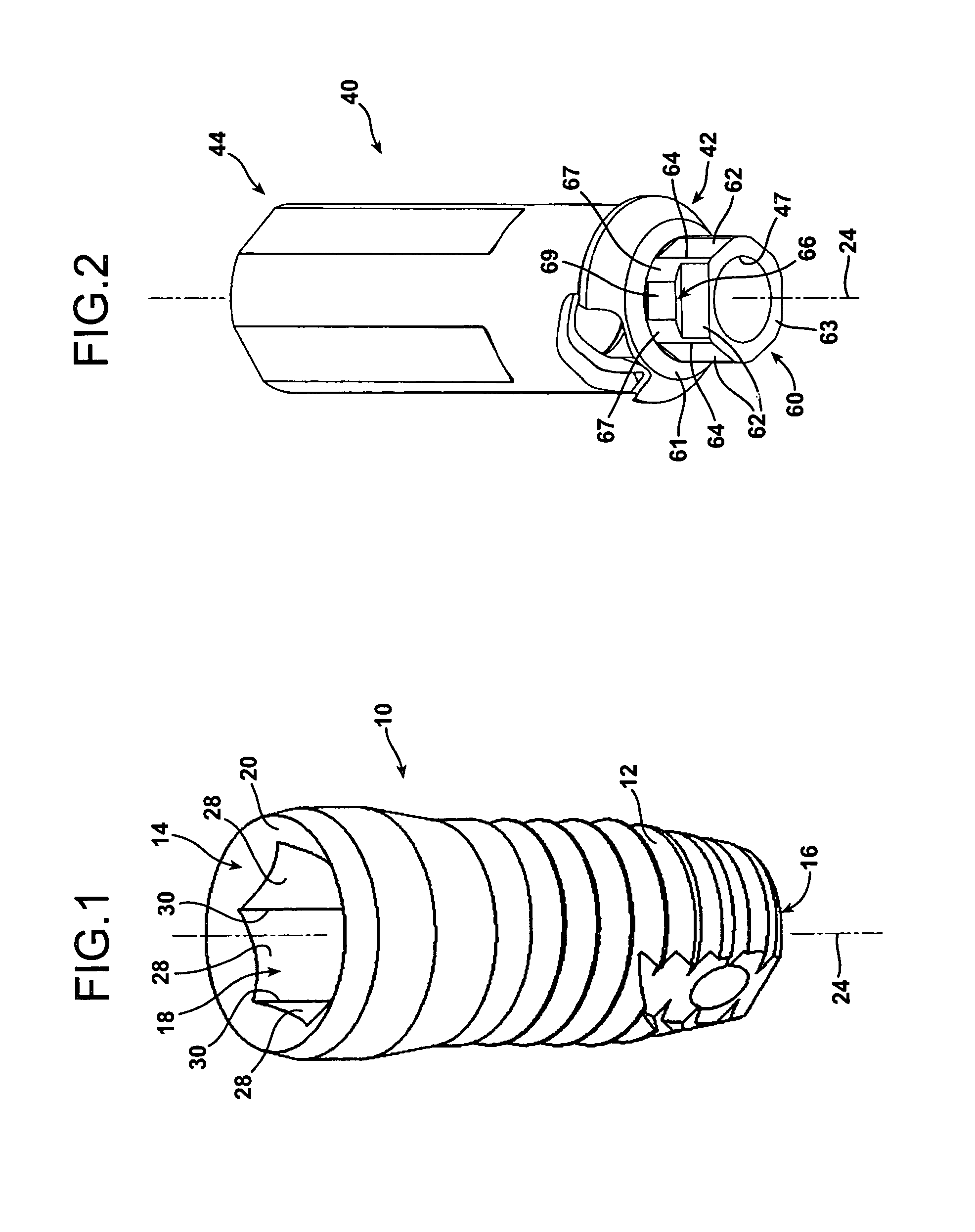
[0047]FIGS. 1 and 17 through 20 illustrate an endosseous dental implant member 10 of the type utilized for endosseous dental implants in the jaw of a patient. The endosseous dental implant member 10 is typically fabricated as a titanium structure having external threads 12 designed to be screwed into the jaw bone of a patient and penetrate into the bone to anchor the implant member 10 relative to the patient's jaw. The implant member 10 has a gingival end 14 and an opposite osseous end 16. When the implant member 10 is installed in the jaw of the patient, the osseous end 16 resides well into the jaw bone structure of the patient, while the gingival end 14 is located at the surface of the patient's gum in the recessed cavity therein vacated by the tooth being replaced.

[0048]A socket 18 is formed into the structure of the implant member 10 at the gingival end 14 thereof. The socket 18 has a uniform, noncircular cross section throughout, and is preferably of a polygonal configuration. ...


PUM


Abstract

An endosseous dental implant system employs an implant member designed to be embedded into the jawbone of a patient at a location vacated by a missing tooth, and a mating abutment member. Both the abutment member and the implant member have mutually facing gingival ends. A socket of uniform, noncircular cross section throughout is defined into the gingival end of either the implant member or the abutment member while a post of corresponding cross-sectional configuration extends from the gingival end of the other member. At least one, and possibly a plurality, of transversely directed projections are formed on the post. These projections are small enough to allow the post to enter the socket in close fitting, seated engagement therewith, but large enough to create an interference fit between the post and the socket to obstruct twisting of the post within the socket. Apart from the transversely extending projections, the post has a uniform cross sectional shape and dimensions throughout its length.

Description

BACKGROUND OF THE INVENTION[0001]1. Field of the Invention[0002]The present invention relates to osseodontic dental implant systems for tooth replacement in orthodontic patients.[0003]2. Description of the Prior Art[0004]In the field of orthodontics there are several techniques for tooth replacement. Crowns are widely employed for this purpose. However, dental crowns require a sturdy foundation. In the simplest, most desirable and least costly procedure the natural structure of the root of a tooth is utilized as the foundation to which the crown is anchored. However, in some instances, this is impractical since a tooth may be so badly damaged due to disease or injury that the entire tooth must be removed.[0005]In such a situation one option is the use of an endosseous dental implant system. In such a system an implant member is inserted into the jaw of a patient. Very typically the implant member will be externally threaded with self-tapping screw threads that anchor the implant mem...

Claims


Application Information

Patent Timeline
Patent Type & Authority Patents(United States)
IPC IPC(8): A61C8/00
CPCA61C8/005A61C8/0069A61C8/006A61C8/0066A61C8/0054A61C8/0059
Inventor RASSOLI, JEFF
Owner RASSOLI JEFF
Why Eureka
Try Eureka