Belt tensioning device

a technology of tensioning device and belt, which is applied in the direction of belt/chain/gearing, mechanical equipment, gearing, etc., can solve the problems of needing considerable additional means and damage, and achieve the effect of reducing production costs and simplifying design and production technology

Inactive Publication Date: 2006-09-12
MUHR UND BENNDER KG
View PDF25 Cites 33 Cited by
  • Summary
  • Abstract
  • Description
  • Claims
  • Application Information

AI Technical Summary

Benefits of technology

[0010]It is, therefore, an object of the present invention to simplify the design and the production technology of a belt tensioning device in such a way that, above all, it can be produced more cost-effectively than prior art belt tensioning devices, without attendant disadvantages.
[0012]The present invention provides a tensioning device for a traction mechanism including a receiving and mounting housing, a roller carrier pivotably connected to the mounting housing, a bearing which radially supports the roller carrier relative to the mounting housing, a spring between the roller carrier and the mounting housing for applying a tensioning force, and a damping device. The damping device includes a damping bush which, by friction, dampens any movement between the roller carrier and the mounting housing in such a way that damping is greater in the direction of an increasing tension force than in the direction of decreasing tension force. A flat band spring applies the friction force to the damping bush. The flat band spring is secured, at a first end, to the receiving and mounting housing in a rotationally fast way, and at a second end to the damping bush in a rotationally fast way.
[0013]In belt tensioning devices of the type generally referred to herein, the damping effect which compensates for or reduces slip and vibrations is achieved by friction which occurs in the case of movements between the roller carrier and the receiving and mounting housing. On the one hand, this requires concentrically extending friction faces which correspond to one another, such friction faces being the inner or outer cylindrical face of the damping bush, and a corresponding friction face at the roller carrier or at the receiving and mounting housing. On the other hand, there is required, in the form of a normal force, a friction force between the friction faces corresponding to one another.
[0016]With the inventive belt tensioning device, the damping bush is substantially rotationally fixed, i.e. it is substantially secured against rotating. In this regard, “substantially” indicates that any movements between the roller carrier and the receiving and mounting housing lead to minimum rotational movements of the damping bush. Such minimum rotational movements of the damping bush are due to the fact that the friction force between the mutually corresponding friction faces leads to a torque acting on the damping bush. As the damping bush is not actually fixed rigidly, but is fixed resiliently by the flat band spring, the torque acting in the damping bush also results in a rotational movement of the damping bush. The minimal rotational movement of the damping bush leads to a minimal change in the diameter of the flat band spring which, either partially or fully, embraces the damping bush. As a result, there occurs a change in the friction force originating from the flat band spring, and thus also in the damping effect.

Problems solved by technology

The disadvantage of the prior art belt tensioning devices is that, on the one hand, due to the unavoidable wear of the cone-type friction bearing, the roller carrier moves axially relative to the receiving and mounting housing and, on the other hand, the damping effect in the direction of load application, i.e. in the direction of an increasing tensioning force, is identical to the damping effect in the direction of load relief, i.e. in the direction of a decreasing tensioning force.
The first variant is disadvantageous in that there is a need for considerable additional means, in particular, the additionally required helical spring.
The second variant is disadvantageous in that the design of the spring which serves to apply the tensioning force also determines the damping characteristics of the belt tensioning device.

Method used


Image

  • Belt tensioning device
  • Belt tensioning device
  • Belt tensioning device

Examples


Embodiment Construction

[0027]While the present invention is described with respect to a belt tensioning device, the present invention may be adapted and utilized for tensioning other traction mechanisms. Thus, although the following components are described for a constructed embodiment, these specific components are included as examples and are not meant to be limiting.

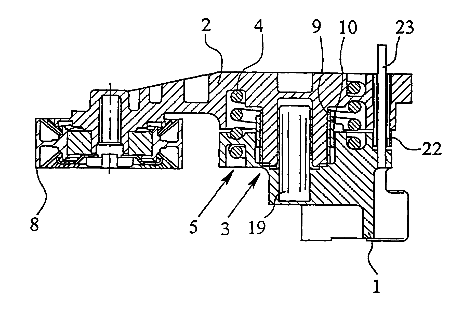
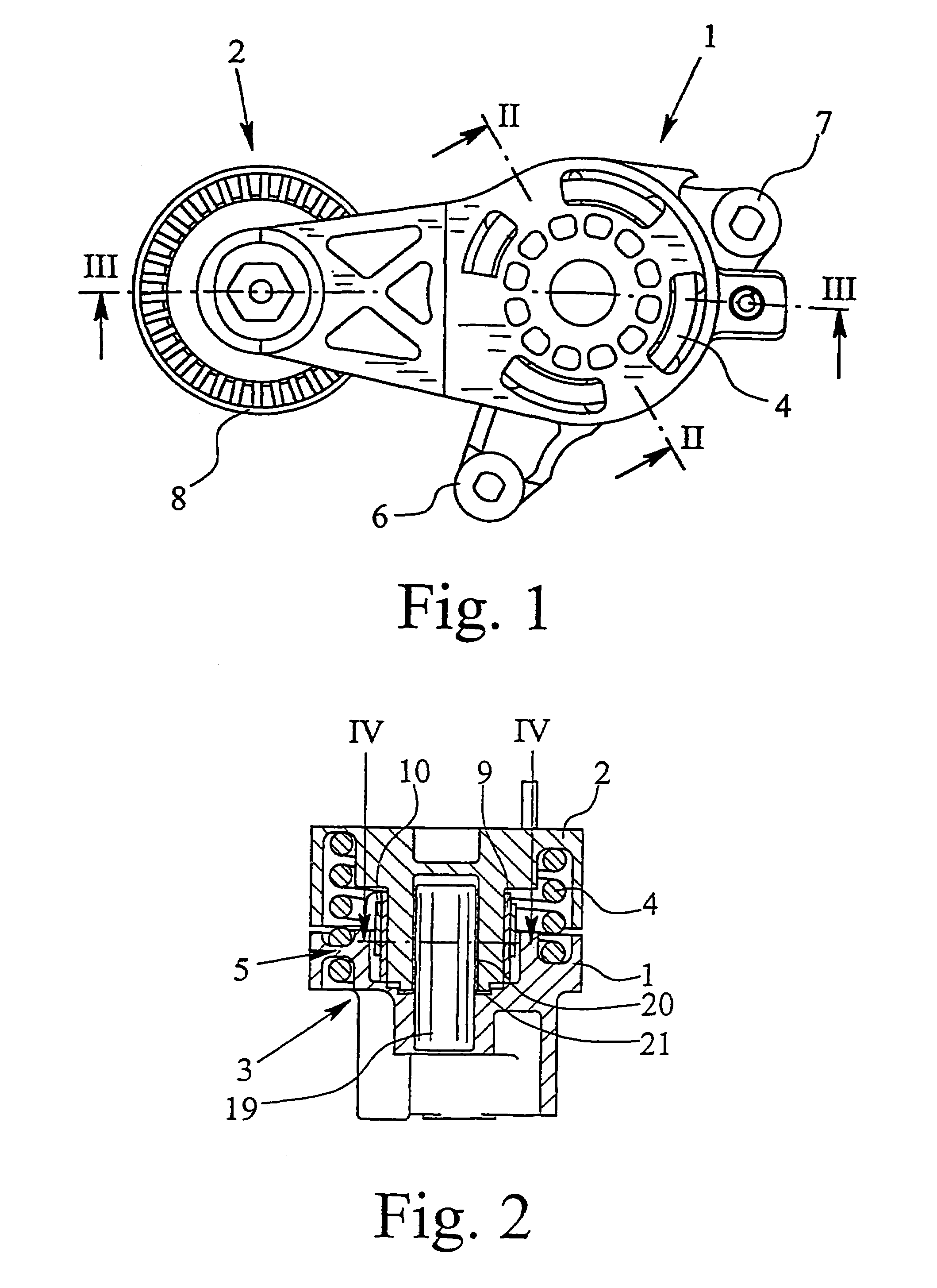
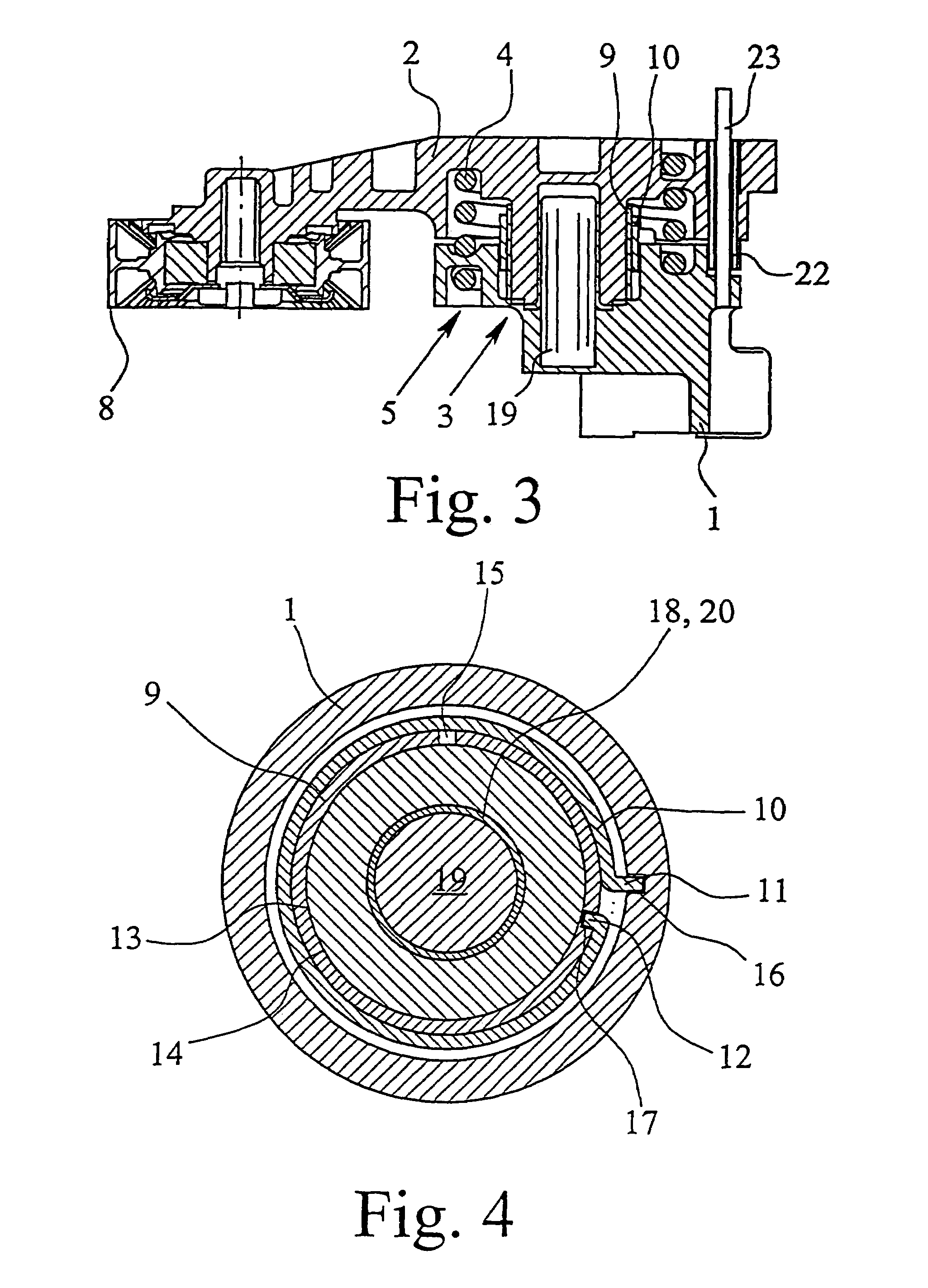
[0028]The Figures show a tensioning device for traction means, namely a belt tensioning device. The belt tensioning device comprises a receiving and mounting housing 1, a roller carrier 2 which is pivotably connected to the receiving and mounting housing 1, a bearing 3 which radially and axially supports the roller carrier 2 relative to the receiving and mounting housing 1, a spring which applies the tensioning force and is arranged between the roller carrier 2 and the receiving and mounting housing 1, which spring, in the embodiment shown, is a helical spring 4 in the form of a leg spring, as well as a damping device 5.

[0029]As shown in FI...


PUM


Abstract

A tensioning device for attraction mechanism including a receiving and mounting housing, a roller carrier pivotably connected to the mounting housing, a bearing which radially supports the roller carrier relative to the mounting housing, a spring between the roller carrier and the mounting housing for applying a tensioning force, and a damping device. The damping device includes a damping bush which, by friction, dampens any movement between the roller carrier and the mounting housing in such a way that damping is greater in the direction of an increasing tension force than in the direction of decreasing tension force. A flat band spring applies the friction force to the damping bush. The flat band spring is secured, at a first end, to the receiving and mounting housing in a rotationally fast way, and at a second end to the damping bush in a rotationally fast way.

Description

CROSS-REFERENCE TO RELATED APPLICATION[0001]This is a Continuation of U.S. patent application Ser. No. 10 / 189,661 filed on Jul. 3, 2002 now abandoned.TECHNICAL FIELD[0002]The present invention relates to a tensioning device for a traction means, such as a belt tensioning device.BACKGROUND OF THE INVENTION[0003]The invention relates to a tensioning device for traction means, such as a belt tensioning device, having a receiving and mounting housing, a roller carrier pivotably connected to the receiving and mounting housing, a bearing which radially and axially supports the roller carrier relative to the receiving and mounting housing, a spring for applying the tensioning force, and a damping device. The spring is arranged between the roller carrier and the receiving and mounting housing and the damping device comprises a damping bush. By friction, the damping device dampens any movements between the roller carrier and the receiving and mounting housing in such a way that the damping e...

Claims


Application Information

Patent Timeline
Patent Type & Authority Patents(United States)
IPC IPC(8): F16H7/08F16H7/12F16H7/10
CPCF16H7/1218F16H2007/084F16H2007/081F16H7/10
Inventor ASBECK, JOCHENBERNDT, THOMASJUD, JOACHIMBONSE, RUDOLF
Owner MUHR UND BENNDER KG
Why Eureka
Try Eureka