Sealing bead

Inactive Publication Date: 2006-09-12
YSF AUTOMOTIVE SYST
View PDF13 Cites 9 Cited by
  • Summary
  • Abstract
  • Description
  • Claims
  • Application Information

AI Technical Summary

Benefits of technology

[0009]In accordance with one aspect of this invention, a fuel system component for a vehicle comprises a wall structure wherein at least one portion of the wall structure includes a barrier layer for inhibiting permeation of fuel vapours through the wall structure of the fuel system component. The fuel system component has at least one area of barrier discontinuity. The fuel system component includes a bead which comprises material for inhibiting permeation of hydrocarbon vapours and the bead overlies the area of barrier discontinuity. The outer layer of the wall structure and at least a portion of the bead are comprised of complimentary heat fusible materials for sealing the bead to the wall structure over the area of barrier discontinuity.
[0010]In another aspect of the invention, a process for inhibiting fuel vapour permeation in a component for storing or conveying hydrocarbon fuels, where the component includes an area of barrier discontinuity

Problems solved by technology

It has been discovered that the pinch off area which occurs in the molding operation may be a source of fuel permeation.
This occurs because of breach or exposure of the barrier layer in the pinching process or in the subsequent process of flash removal.

Method used


Image

  • Sealing bead
  • Sealing bead
  • Sealing bead

Examples


Embodiment Construction

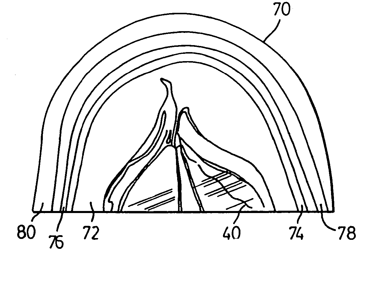
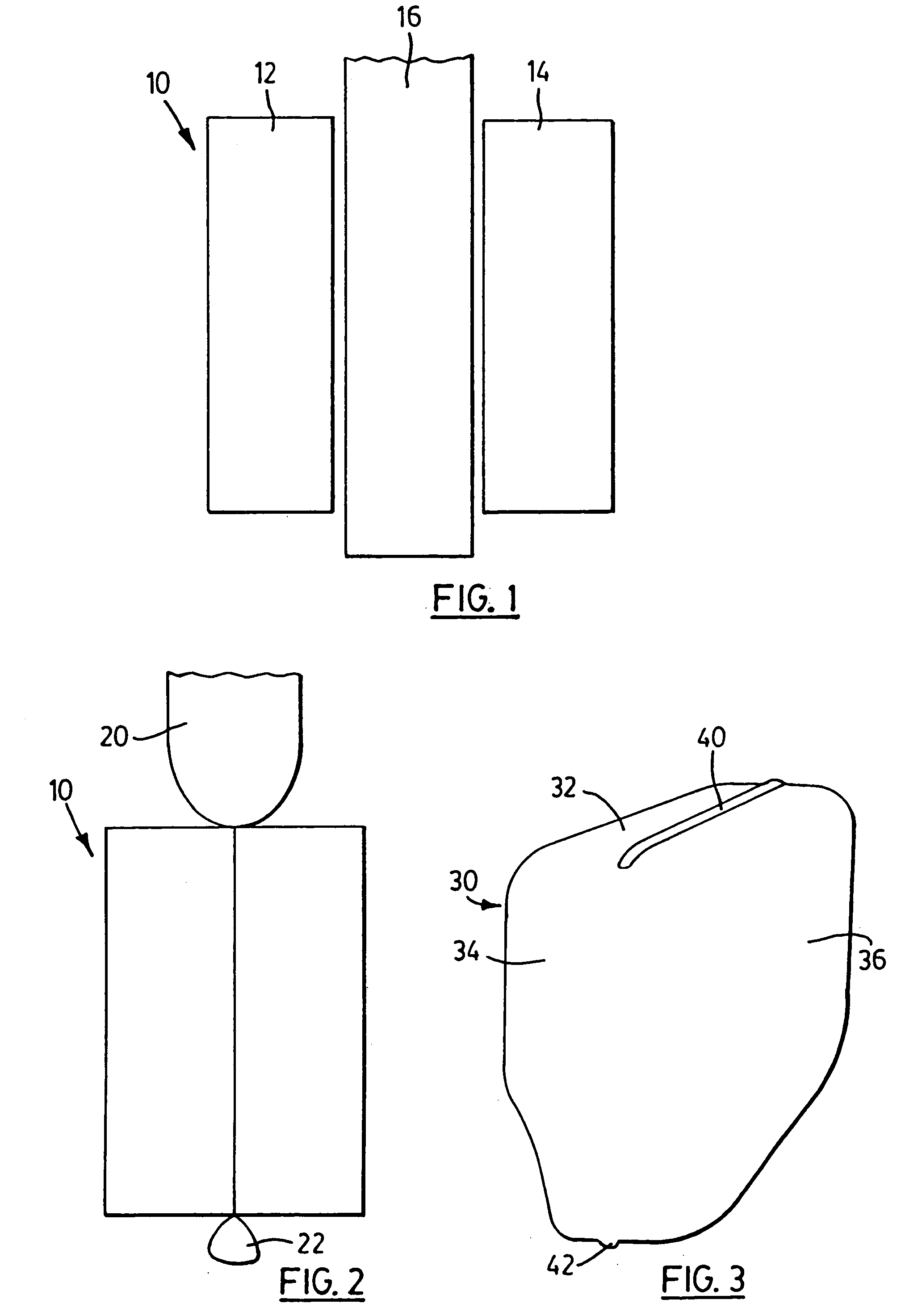
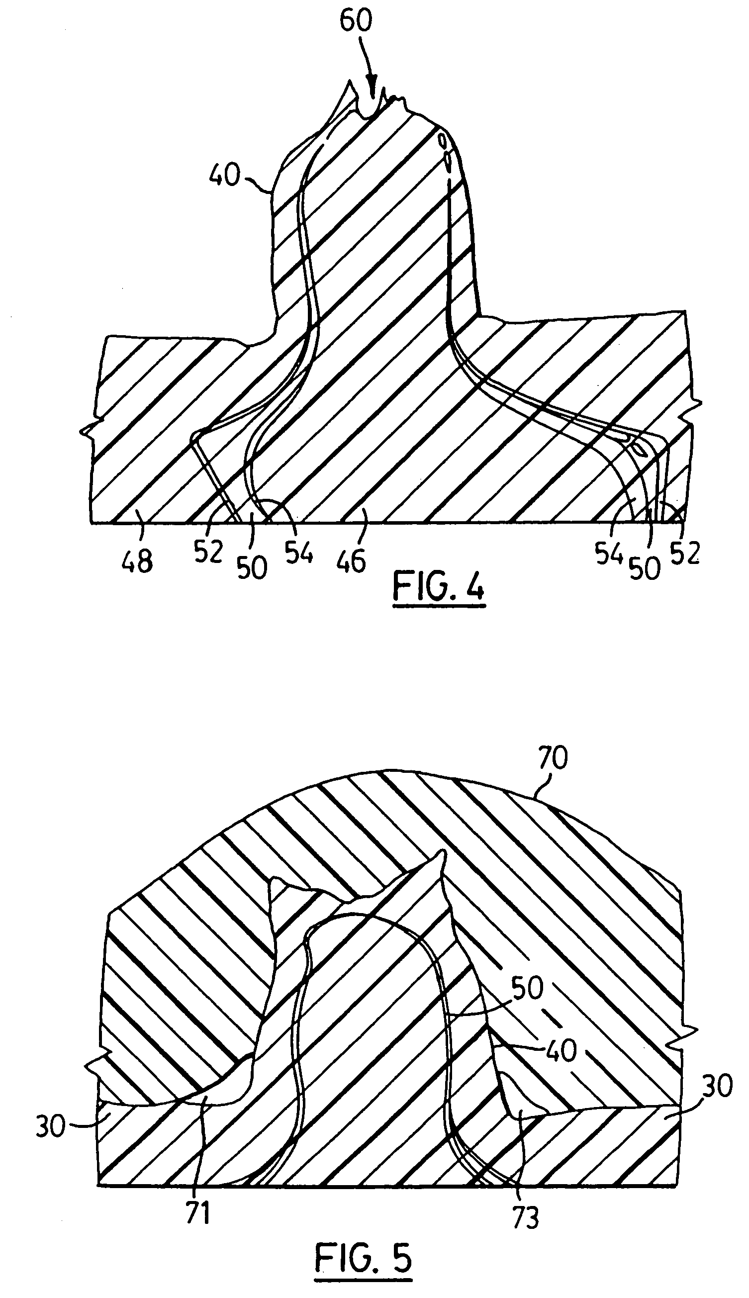
[0022]FIG. 1 illustrates the general arrangements of components in typical blow molding procedure. A blow mold 10 comprises complimentary mold portions 12 and 14. The mold portions 12 and 14 are movable horizontally, as shown in FIG. 1, from an open position to a closed position as shown in FIG. 2. When the mold portions 12 and 14 are in the open position, a parison 16 is extruded from an extrusion head (not shown). The parison will hang substantially vertically from the extrusion head. When the parison has been extruded and has the appropriate length, the mold portions 12 and 14 are closed. The closed configuration is illustrated in FIG. 2.

[0023]With reference to FIG. 2, it will be noted that there is a small portion of the parison indicated diagrammatically above the mold 10 as 20. There will also be a small amount of parison material extending beyond the mold indicated generally at 22. In order to achieve typical blow molding, the parison must form an air tight enclosure. Thus, t...


PUM


Abstract

Fuel system components for vehicles may be made from polyethylene components which are typically blow molded. To inhibit fuel vapour permeation, the polyethylene is often co-extruded into a parison with the parison comprising a barrier layer. Upon trimming flash or in the mold closure itself, the barrier layer may be ruptured. Sealing of areas of discontinuity in the fuel system component to inhibit hydrocarbon vapour pass through is achieved by sealing the area of barrier discontinuity with a sealing bead which has the necessary barrier properties. The barrier properties may be inherent in the sealing bead material or in a barrier layer extruded into the sealing bead.

Description

[0001]This application is a divisional of U.S. application Ser. No. 10 / 274,453 filed Oct. 21, 2002 now U.S. Pat. No. 6,811,739, which is a divisional of U.S. application Ser. No. 09 / 512,366 filed Feb. 25, 2000, now U.S. Pat. No. 6,467,643 issued Oct. 22, 2002.FIELD OF THE INVENTION[0002]This invention relates to fuel system components and in particular to plastic structures such as fuel tanks and the like which may be made using blow molding techniques. In particular, the invention relates to a method and structure for sealing such blow molded fuel system components to further inhibit hydrocarbon vapour permeation through the finished structure.BACKGROUND OF THE INVENTION[0003]Hydrocarbon containing fuels such as gasoline are the most common power source for internal combustion engines. Gasoline must be carried by the vehicle, usually in a fuel tank. Heretofore fuel tanks have been manufactured from metal. More recently however, much work has been done on fuel tanks made from plasti...

Claims


Application Information

Patent Timeline
IPC IPC(8): B29C47/02B60K15/03B29C48/09B29C48/10B29C48/12B29C48/19B29C49/04B29C49/22B29C49/42B29C65/00B29K23/00B29L9/00B29L22/00B29L31/30F02M37/00
CPCB29C66/038B29C47/0023B29C47/0026B29C47/003B29C47/0054B29C49/04B29C47/062B29C2791/001B29K2995/0067B29L2031/7172B60K15/03177B29C65/02B29C66/71B29C66/72341B29C48/09B29C48/10B29C48/12B29C48/0017B29C48/19B29K2077/00B29K2023/086B29K2023/06
Inventor SADR, CHANGIZE
Owner YSF AUTOMOTIVE SYST
Why Eureka
Try Eureka