Highly efficient permanent magnet brushless motor

a brushless motor, high-efficiency technology, applied in the direction of magnet circuit rotating parts, magnetic circuit shape/form/construction, windings, etc., can solve the problems of inefficiency, energy efficiency, inability to meet the ideal, etc., to achieve superior cogging performance, high torque efficiency, and low total harmonic distortion

Inactive Publication Date: 2006-09-12
KOLLMORGEN CORP
View PDF4 Cites 16 Cited by
  • Summary
  • Abstract
  • Description
  • Claims
  • Application Information

AI Technical Summary

Benefits of technology

[0009]The unique advantages of the present invention are achieved by providing slot / pole ratios that are less than one, but greater than 0.5. These slot / pole ratios enable high torque efficiencies.
[0010]A further aspect of the present invention provides slot / pole combinations that will provide superior cogging performance.
[0011]A further aspect of the present invention provides slot / pole combinations that will provide balanced windings.
[0012]A further aspect of the present invention provides slot / pole combinations that will provide low total harmonic distortion.

Problems solved by technology

This ideal, however, cannot be met.
When designing high performance servomotors cost, energy efficiency, and size are often of lower priority than power and performance quality.
This solution, however, creates inefficiencies of its own, mainly due to the need for a gearbox.
Gearboxes are expensive, inefficient, noisy, producers of torque ripple which are prone to wear requiring additional maintenance expense.
The use of a gearbox also prevents the tight integration of the motor and the driven device due to the backlash of the gears and due to the lower torsional resonances in the required couplings and the gearbox itself.
This results in lower system bandwidths, reducing the system performance in an overall physically larger system with extra room required to house the gearbox.
Accordingly, direct drive systems do away with the gearbox, its system limitations, and its associated expense.
Loss of the gearbox, however, also results in the loss of its functional benefits, namely, the ability to run the motor at its most efficient speed and then use gearing to provide the required torque at the required speed.
Also, with the motors running at lower speeds cogging, speed ripple, and torque ripple become more significant issues.
Of course, the need for a relatively larger, more expensive, motor at least partially negates the cost benefit attained by removing the gearbox.

Method used


Image

  • Highly efficient permanent magnet brushless motor
  • Highly efficient permanent magnet brushless motor
  • Highly efficient permanent magnet brushless motor

Examples


Embodiment Construction

[0017]The present invention provides a highly optimized motor design enabling an increase in torque compared to a similarly sized motor of traditional design. Additionally, the present invention enables motors that provide smooth, ripple free, torque operation at low speeds. These advances are provided through unique efficient motor design topologies not found in the prior art.

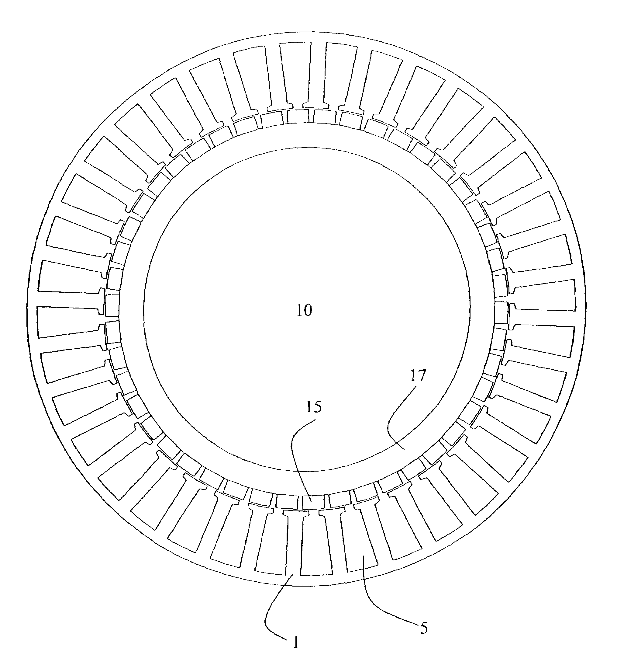
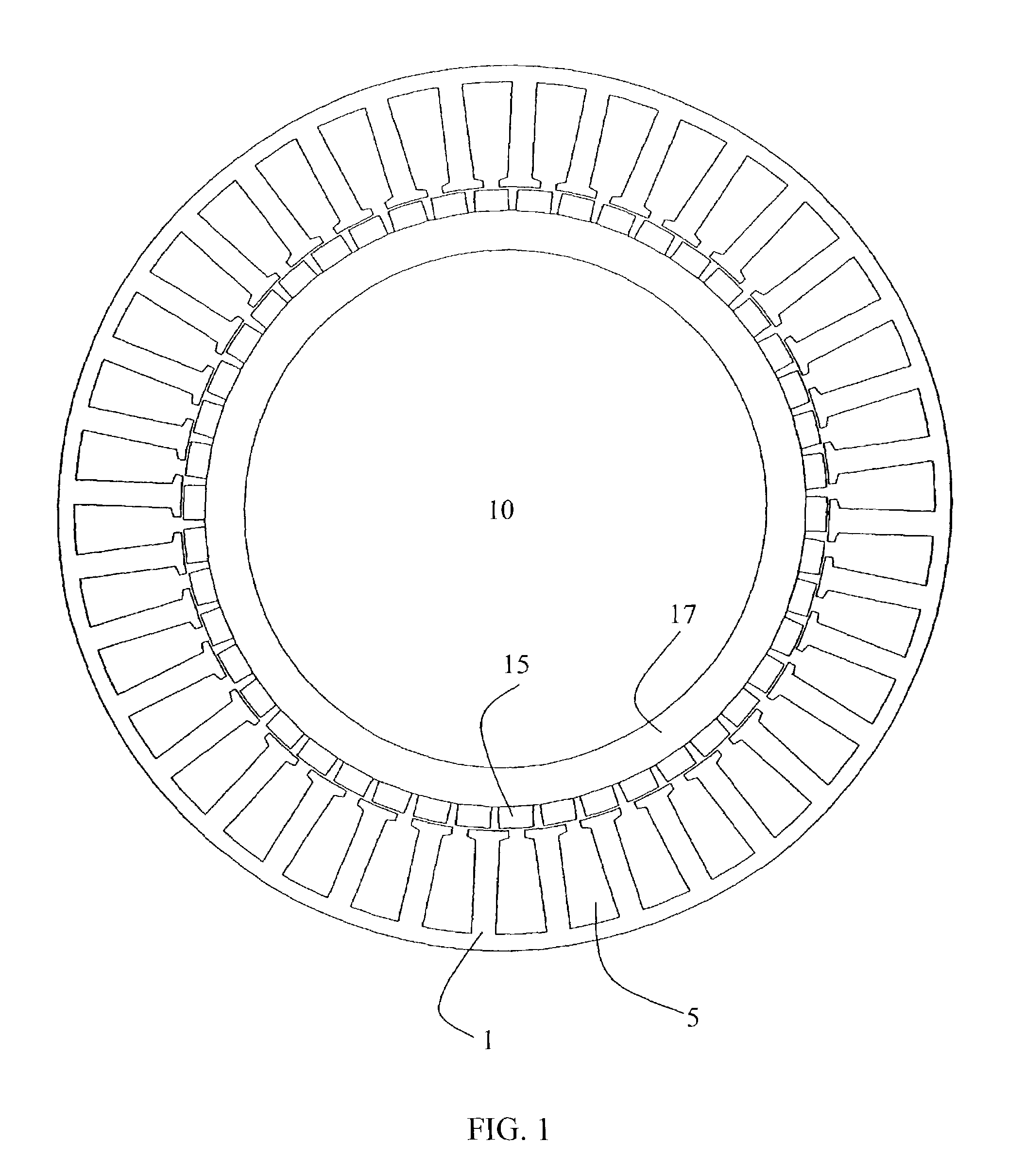
[0018]The unique aspects of the present invention are best described through reference to the attached figures. An exemplary embodiment of the present invention is shown in FIG. 1. This motor shares many of the features of a conventional permanent magnet brushless motor. The wound assembly 1 has permeable laminations with slots 5 and insulated copper wire wound in the slots. The insulated wire is wound into coils with a span of 1 tooth, i.e. each coil is wound around one tooth. The field assembly 10 has magnetic poles 15 arranged on a permeable structure 17.

[0019]The present invention achieves its surprisingly...


PUM


Abstract

The present invention provides a highly optimized motor design enabling an increase in torque compared to a similarly sized motor of traditional design. Additionally, the present invention enables motors that provide smooth, ripple free, operation at low speeds. These advances are provided through disclosure of slot / pole ratios that provide the stated benefits.

Description

FIELD OF THE INVENTION[0001]The present invention relates generally to permanent magnet motors, and more particularly, to servomotors capable of efficiently producing high torque with low torque ripple including both low cogging torque components and low MMF harmonic torque components.BACKGROUND OF THE INVENTION[0002]Efficiency is always a major goal of any motor design. Ideally, motors would be small, powerful with low torque ripple, inexpensive, and energy efficient. This ideal, however, cannot be met. For real world designs tradeoffs must be made and goals must be prioritized.[0003]When designing high performance servomotors cost, energy efficiency, and size are often of lower priority than power and performance quality. Servomotors, generally, must produce smooth and powerful torque over a range of speeds on a continuous basis over time and on a peak short term basis, without cogging, torque ripple, or speed ripple. Furthermore, many servo applications particularly require high ...

Claims


Application Information

Patent Timeline
Patent Type & Authority Patents(United States)
IPC IPC(8): H02K1/00H02K21/16H02K29/03
CPCH02K29/03H02K21/16H02K1/27H02K3/28
Inventor BREWSTER, JEFFERY T.BROWN, GERALD W.
Owner KOLLMORGEN CORP
Why Eureka
Try Eureka