Efficiently testable display driving circuit

a display driving circuit and testable technology, applied in static indicating devices, instruments, electroluminescent light sources, etc., can solve the problems of inability to uniformly put out light, take too much time, and vary test results, etc., and achieve the effect of efficient testability

Inactive Publication Date: 2006-09-12
LAPIS SEMICON CO LTD
View PDF6 Cites 10 Cited by
  • Summary
  • Abstract
  • Description
  • Claims
  • Application Information

AI Technical Summary

Benefits of technology

[0016]An object of the present invention is to provide an efficiently testable device for driving a dot matrix display panel.

Problems solved by technology

If the constant-current sources 11i do not output uniform amounts of current, the pixel elements cannot put out uniform amounts of light.
One problem with this type of test is that it takes too much time, since the probes have to be moved repeatedly from one terminal to another, and each time a probe is moved to a new terminal, a certain time must be allowed before the flow of current stabilizes and accurate values can be measured.
Another problem is that the test results tend to vary according to random variations in the force with which the probes make contact with the terminals, the area of contact, and other such factors.
To ensure the quality of the display, tight tolerances are set on the test results, so random variations can easily cause a device that actually meets its specifications to be rejected as defective.

Method used


Image

  • Efficiently testable display driving circuit
  • Efficiently testable display driving circuit
  • Efficiently testable display driving circuit

Examples


Embodiment Construction

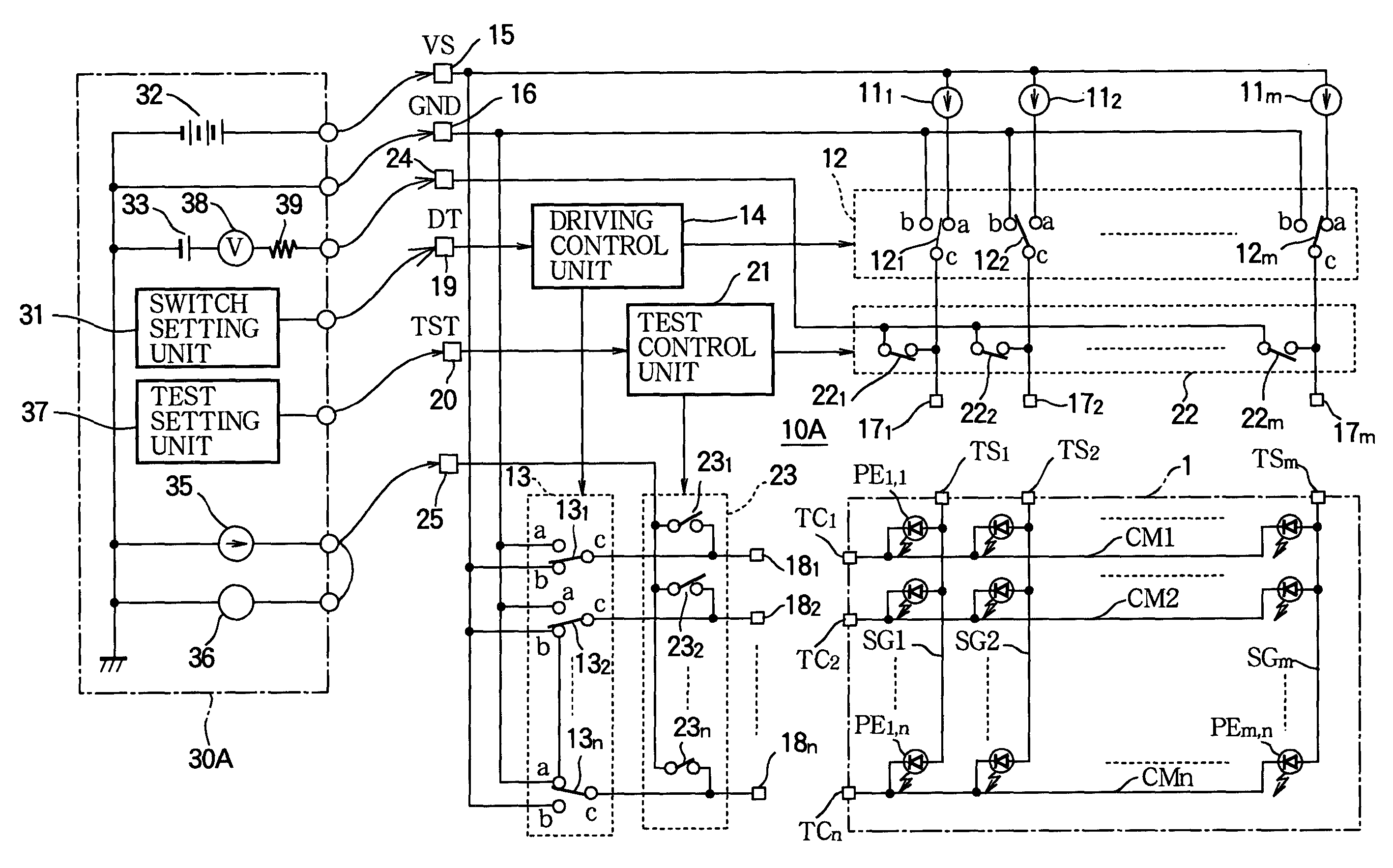
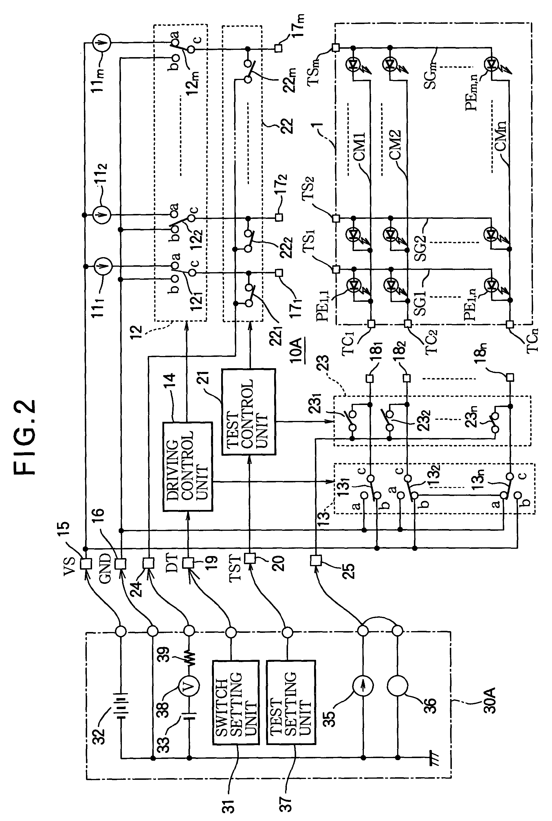
[0027]An embodiment of the invention will now be described with reference to FIG. 2, in which elements similar to the corresponding elements in FIG. 1 are indicated by the same reference characters.

[0028]The display driving circuit 10A in FIG. 2 drives an organic electroluminescent panel 1 to generate a dot matrix display. The organic electroluminescent panel 1 is of the conventional type comprising an intersecting grid of data lines SGi and scanning lines CMj with organic electroluminescent pixels PEi,j disposed at the grid intersections, the pixels being connected by their anodes to the data lines and by their cathodes to the scanning lines. The data lines SGi have respective terminals TSi (i=1 to m) at which they are connected to the display driving circuit 10A; the scanning lines CMj have respective terminals TCj (j=1 to n) at which they are connected to the display driving circuit 10A (m and n are integers greater than one).

[0029]The display driving circuit 10A includes the con...


PUM


Abstract

A device for driving a dot matrix display panel has a number of first terminals that can be connected to different signal lines in the dot matrix display panel, to carry current to or from picture elements in the dot matrix display panel. The invented device also has a second terminal and a set of switches that can selectively connect the first terminals to the second terminal. These switches enable a measurement device connected to the second terminal to measure electrical parameters at the first terminals individually, so that the electrical parameters of the device can be tested efficiently and accurately, without having to contact each of the first terminals with a probe.

Description

BACKGROUND OF THE INVENTION[0001]1. Field of the Invention[0002]The present invention relates to a display driving circuit for a current-driven display panel such as an electroluminescent (EL) panel, and more particularly to the testability of the display driving circuit.[0003]2. Description of the Related Art[0004]FIG. 1 shows a conventional display driving circuit, disclosed in Japanese Unexamined Patent Application Publication No. 11-95723, and illustrates how it is tested. The display driving circuit 10 drives an organic electroluminescent panel 1 to create a dot matrix display. The organic electroluminescent panel 1 comprises an intersecting grid of m data lines SGi (i=1 to m) and n scanning lines CMj (j=1 to n), where m and n are integers greater than one. Organic electroluminescent picture elements or pixels PEi,j are disposed at the intersections of the grid; each pixel PEi,j has an anode coupled to data line SGi and a cathode coupled to scanning line CMj.[0005]The display d...

Claims


Application Information

Patent Timeline
Patent Type & Authority Patents(United States)
IPC IPC(8): G09G3/30H05B33/12G09G3/00G09G3/20H01L51/50
CPCG09G3/006Y10S345/904
Inventor SATOH, SHINICHI
Owner LAPIS SEMICON CO LTD
Why Eureka
Try Eureka