Structure for mounting flat panel display

Inactive Publication Date: 2006-09-12
LG DISPLAY CO LTD
View PDF6 Cites 237 Cited by
  • Summary
  • Abstract
  • Description
  • Claims
  • Application Information

AI Technical Summary

Benefits of technology

[0013]An advantage of the present invention is to provide a structure for mounting a flat panel display devices in which the weight, thickness and stability is improved.
[0014]Additional features and advantages of the invention will be set forth in the description which follows and in part will be apparent from the description or may be learned by practice of the invention. The objectives and other advantages of the invention will be realized and attained by the structure particularly pointed out in the written description and claims hereof as well as the appended drawings.
[0015]To achieve these and other advantages and in accordance with the purpose of the present invention, as embodied and broadly described, a structure for mounting a flat panel display device includes a flat panel display module for outputting an image, a rear cover to which the display module is fitted, and a front cover fitted to a frontal side of the rear cover to c

Problems solved by technology

However, the related art LCD device has numerous problems.
Additionally, the metallic sash 23

Method used


Image

  • Structure for mounting flat panel display
  • Structure for mounting flat panel display
  • Structure for mounting flat panel display

Examples


Example

[0029]Reference will now be made in detail to an embodiment of the present invention, example of which is illustrated in the accompanying drawings. Wherever possible, the same reference numbers will be used throughout the drawings to refer to the same or like parts.

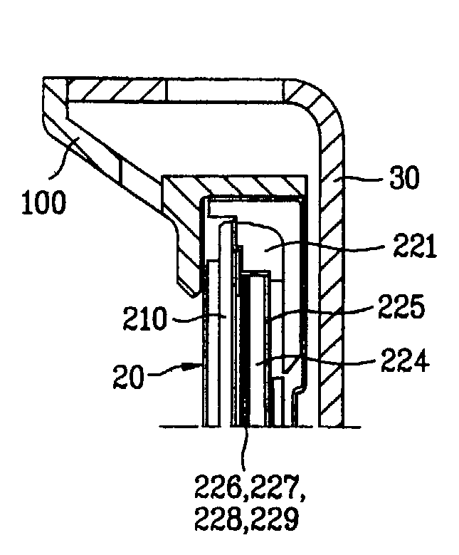
[0030]FIGS. 4 to 8 generally illustrate an LCD device including structures for mounting flat panel displays. The LCD device includes a rear cover 30 made of synthetic resin that maybe hinge-fitted to a notebook computer body (not shown). The notebook computer body (not shown) can include a calculation device, a memory device, a peripheral device, and a keyboard, and the like. The LCD module 20 for outputting an image is fitted to the rear cover 30. A front bezel 100 made of synthetic resin is fitted to a frontal edge of the rear cover 30 thereby covering an edge of the LCD module 20.

[0031]The LCD module 20 includes a liquid crystal (LC) panel 210 for outputting an image, spread sheets 226 and 229, prism sheets 227 and 228...


PUM


Abstract

A structure for mounting a flat panel display module constituting a screen display device of a portable computer system wherein the weight and a thickness of a display device are reduced. For example, the structure for mounting a flat panel display includes a display module having a flat panel display panel, a backlight assembly, and a supporting member for supporting edges of the flat panel display panel and the back light assembly, a rear cover to which the display module is fitted, and a front cover fitted to a frontal edge of the rear cover to cover a frontal edge of the display module. In this structure the supporting member is formed at an inner side of the front cover.

Description

[0001]The present invention claims the benefit of Korean Patent Application No. P 2001-41347 filed on Jul. 10, 2001, which is hereby incorporated by reference in its entirety as if fully set forth herein.BACKGROUND OF THE INVENTION[0002]1. Field of the Invention[0003]The present invention relates to a flat panel display and more particularly to a structure for mounting a flat panel display.[0004]2. Discussion of the Related Art[0005]In order to achieve small and lightweight systems such as a monitor of a desktop computer, a notebook computer, a portable computer, a personal digital assistant (PDA), and a portable telephone terminal, flat panel display devices are utilized. The flat panel display device may include a liquid crystal display (LCD), a plasma display panel (PDP), a field emission display (FED), and the like. Flat panel display devices have excellent visual perception, smaller power consumption, and produce less heat when compared to the cathode ray tube (CRT) devices. Ac...

Claims


Application Information

Patent Timeline
IPC IPC(8): G02F1/1333G09F9/00G06F1/16
CPCG06F1/1637G06F1/1616G06F1/16
Inventor YOU, DONG JAE
Owner LG DISPLAY CO LTD
Why Eureka
Try Eureka