Method for compensating timing to start data recording and magnetic disk device using same

Inactive Publication Date: 2006-09-12
HITACHI GLOBAL STORAGE TECH JAPAN LTD +1
View PDF7 Cites 11 Cited by
  • Summary
  • Abstract
  • Description
  • Claims
  • Application Information

AI Technical Summary

Benefits of technology

[0020]The present invention provides techniques, especially applicable in disk devices having separate write and read heads, that compensate for variations in the head ga

Problems solved by technology

In the situation where the deviations in phase and the like is corrected by the PLL circuit after the read gate is asserted, the operation of the PLL circuit may be unstable and the subsequent correction may be impossible if the no signal state continues while the PLL circuit is operated and, therefore, the signal identical to

Method used


Image

  • Method for compensating timing to start data recording and magnetic disk device using same
  • Method for compensating timing to start data recording and magnetic disk device using same
  • Method for compensating timing to start data recording and magnetic disk device using same

Examples


Example

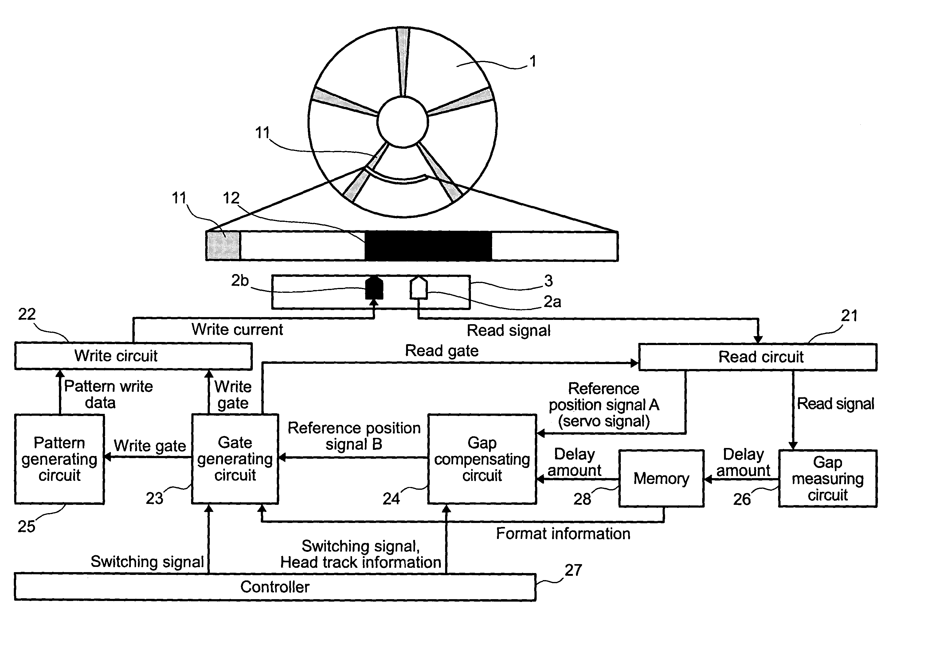
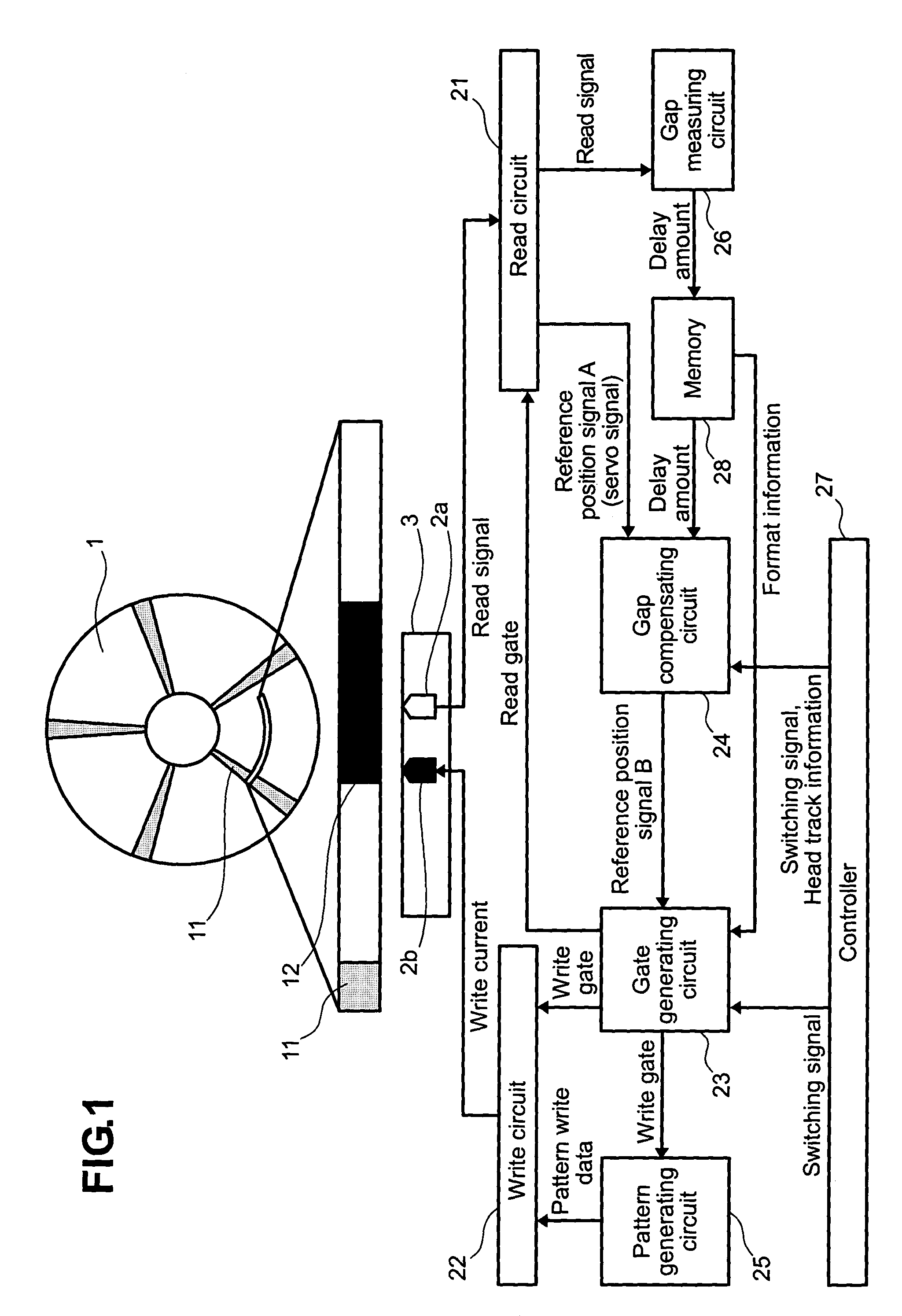
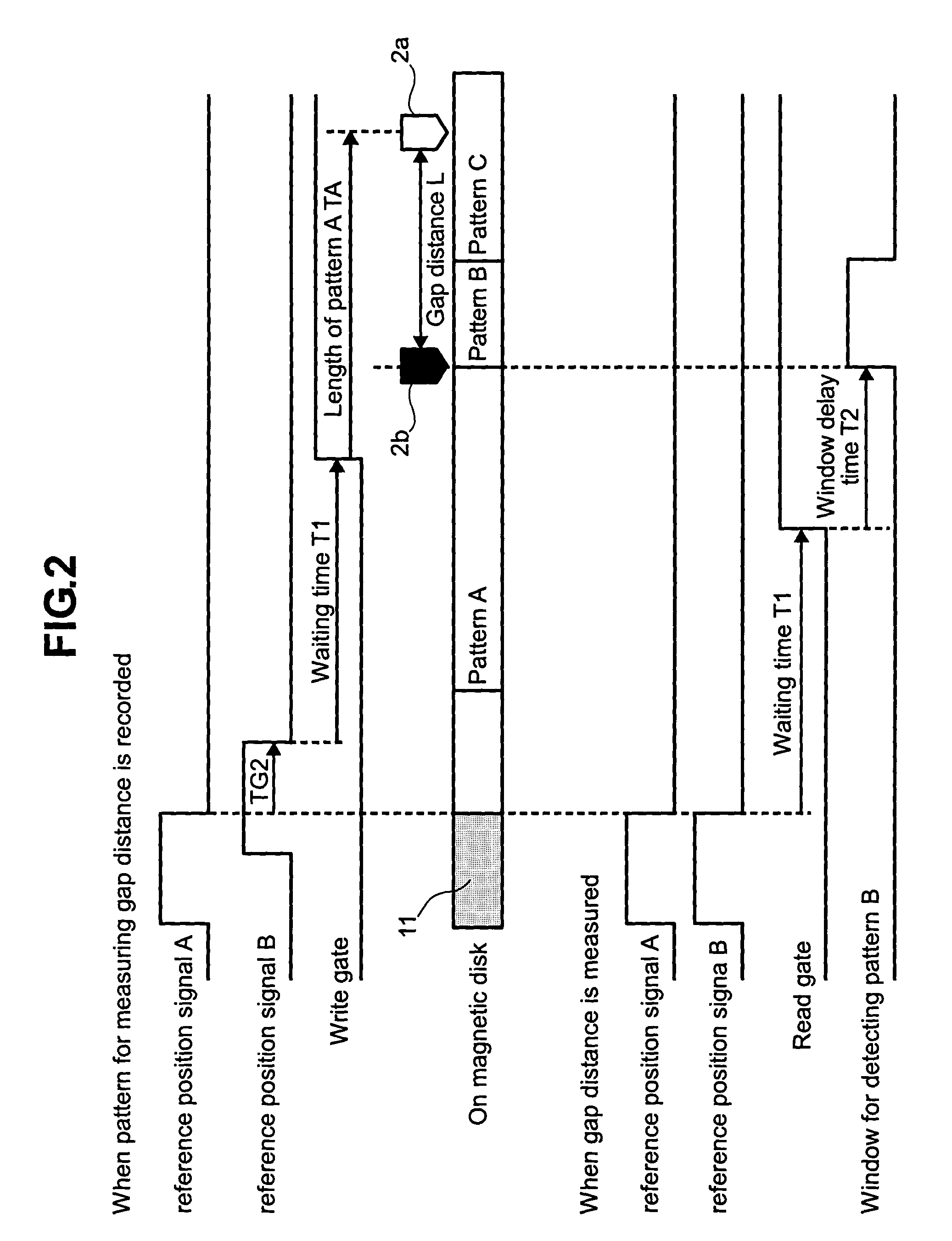
[0037]Hereinafter, a method for compensating timing to start data writing and a magnetic disk device using the same according to an embodiment of the present invention will be described in detail with reference to FIGS. 1, 2, and 3. FIG. 1 is a diagram for describing an overall configuration and features of the magnetic disk device according to the embodiment of the present invention, FIG. 2 is a diagram for describing features for compensating deviations in timing between a write head and a read head according to this embodiment, and FIG. 3 is a diagram showing aspects of the timing to start the writing when the head gap distance between the write head and the read head is either nominal, large, or small according to this embodiment.

[0038]In FIG. 1, the magnetic disk device according to the embodiment of the present invention comprises a write head 2b for writing data on a magnetic disk 1, a write circuit 22 for modulating the data and supplying a write current to the write head 2b...


PUM


Abstract

Head-to-head variations in the head gap distance between write and read heads is compensated by measuring the head gap distance in each head by writing and reading a predetermined unique pattern, and compensating the timing to start the data writing by changing it in a head-to-head manner based on a time gap that corresponds to the measured head gap distance in each head. This allows data to be written at a desired physical position regardless of the variation of the head gap distance, thereby allowing formatting efficiency to be improved.

Description

CROSS-REFERENCE TO RELATED APPLICATIONS[0001]This application claims priority to Japanese Application No. 2003-085870, filed Mar. 26, 2003, the entire disclosure of which is incorporated by reference for all purposes.BACKGROUND OF THE INVENTION[0002]The present invention relates generally to magnetic disk devices having separate heads for writing (recording) and reading (reproducing) data, and more specifically to compensating timing for starting writing to account for different distances between the heads.[0003]FIG. 4 is a diagram showing how the data is typically written and read in a conventional magnetic disk device 1 in which data sectors (minimum addressable units for writing and reading) are arcs formed at specified positions on concentric circles (tracks). Servo signals 11 are written on the magnetic disk 1 in advance and are spaced uniformly in the rotation direction and include information in the radial direction. When the data is written and read in a specified data secto...

Claims


Application Information

Patent Timeline
IPC IPC(8): G11B5/09G11B15/12G11B20/10G11B5/00G11B5/012G11B5/02G11B5/455G11B5/48G11B20/14G11B20/18G11B27/36
CPCG11B5/012G11B5/455G11B20/1403G11B27/36G11B20/1816G11B5/4886G11B2220/2516G11B2005/001G11B2005/0013G11B2220/20G11B5/02
Inventor YOSHIDA, HITOSHIITO, YASUYUKIITOU, KIYOTADA
Owner HITACHI GLOBAL STORAGE TECH JAPAN LTD
Why Eureka
Try Eureka