
Perpendicular magnetic writer with magnetic potential control shield

a magnetic writer and magnetic potential technology, applied in the field of magnetic disk systems, can solve problems such as limiting the achievable recording density, and achieve the effect of increasing the resistance of flux propagation and greater control over the path

Inactive Publication Date: 2006-09-12
HEADWAY TECH INC
View PDF11 Cites 17 Cited by
  • Summary
  • Abstract
  • Description
  • Claims
  • Application Information

AI Technical Summary

Benefits of technology

[0014]These objects have been achieved in a structure that provides greater control over the path taken by the flux, particularly near the surface of the writeable media. The conventional extended return pole of the prior art has been replaced by one whose magnetic potential has been increased relative to both the main and retur...

Problems solved by technology

This is the result of the insufficient field gradients produced by a perpendicular SP head in both the cross-track and down-track directions, thus limiting the achievable recording density.

Method used


Image

  • Perpendicular magnetic writer with magnetic potential control shield
  • Perpendicular magnetic writer with magnetic potential control shield
  • Perpendicular magnetic writer with magnetic potential control shield

Examples


1st embodiment

1st Embodiment

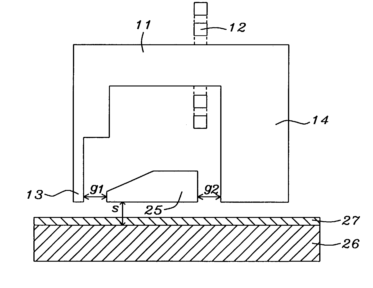
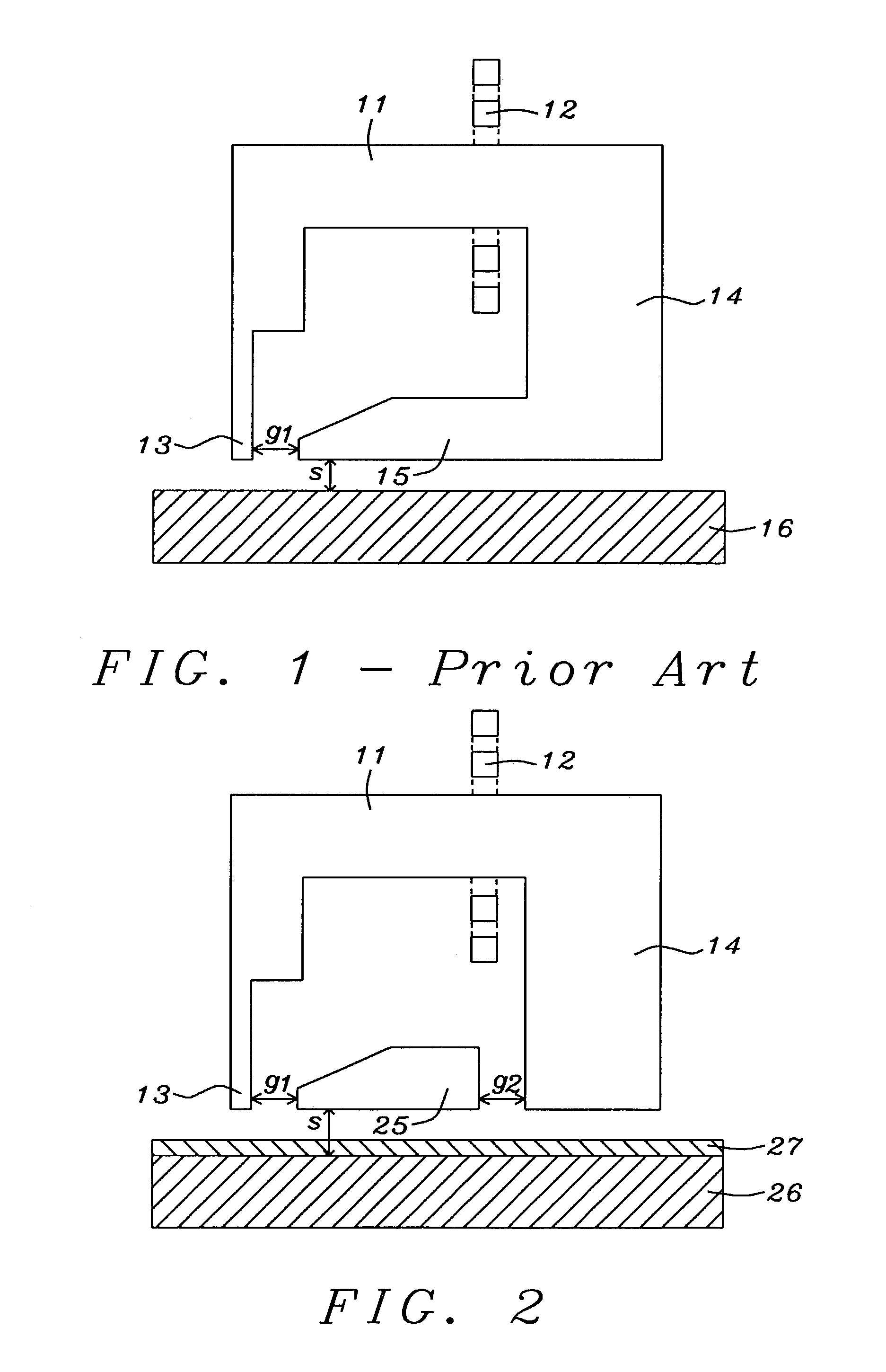
[0023]A first embodiment of the invention is illustrated in FIG. 2. Magnetic yoke 11 may be typically thought of as comprising two parts, a vertical part that terminates in pole tip 13 (typically up to about 2 microns thick and up to about 12 microns long) and a horizontal part (typically between about 1 and 5 microns thick and between about 2 and 12 microns long) that is connected to return pole 14. Suitable materials for the yoke include (but are not limited to) Co, Ni, Fe, and their alloys, including amorphous magnetic materials. Suitable materials for return pole 14 include permalloy and other Co, CoFe, and NiFeCo alloys or amorphous compounds and it is between about 1 and 5 microns thick and between about 2 and 12 microns long. Field coil 12 surrounds the yoke.

[0024]Suitable materials for vertical recording layer 27 include CoCrPtO and CoCrFeB. This layer is typically between about 0.01 and 0.03 microns thick while the underlayer, of magnetically soft material, 26...

2nd embodiment

2nd Embodiment

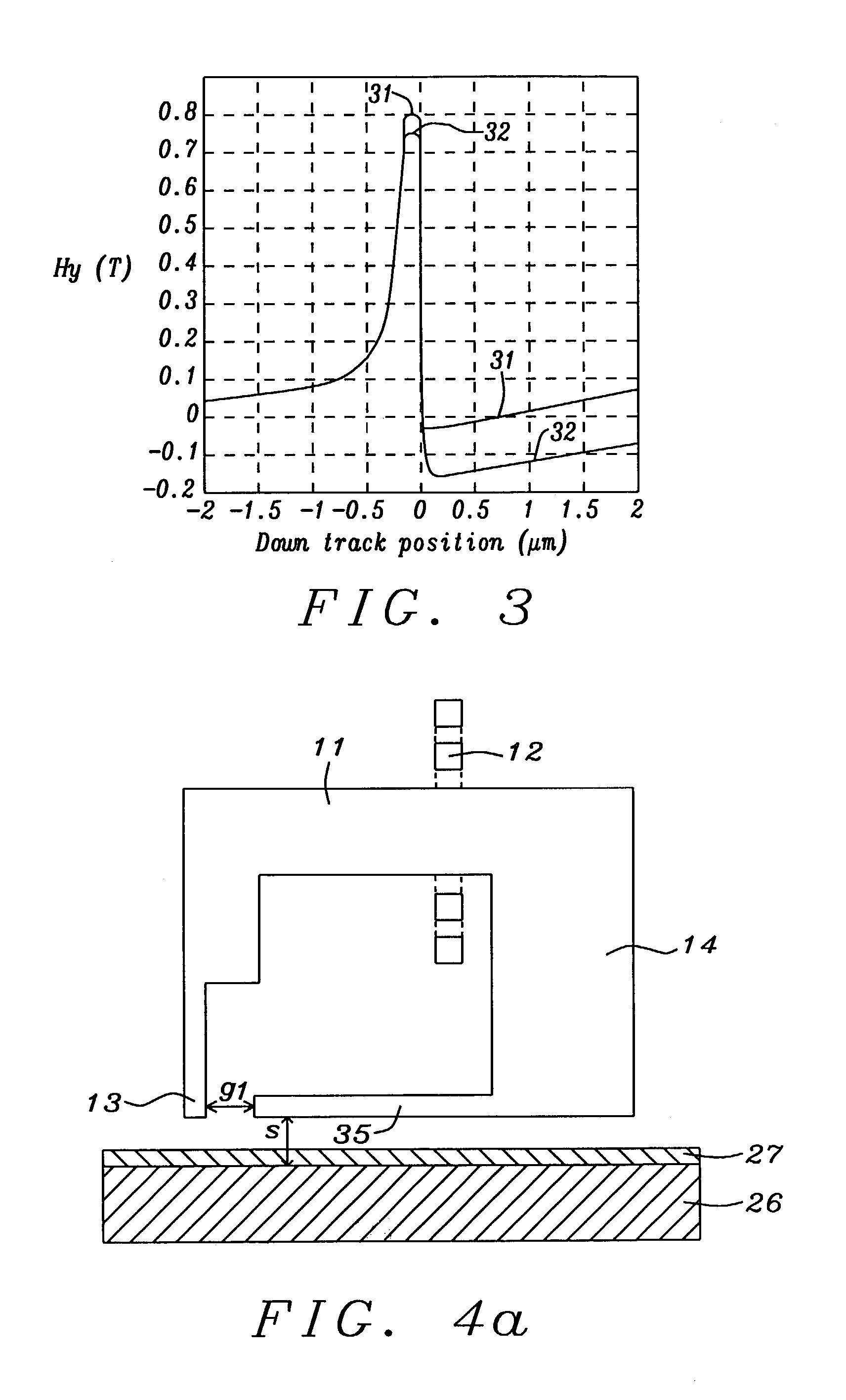
[0029]The concept of magnetic potential / flux leakage control can be also applied to perpendicular writers through a modification of the extended return pole itself. As shown in FIG. 4a, the vertical thickness of the modified extended return pole 35 (which is between about 1 and 10 microns long) is reduced to be of the order of S, making it between about 0.01 and 0.2 microns thick. Suitable materials for this modified extended return pole include NiFe, CoFeNi, FeAlN, CoFe, their alloys, and amorphous magnetic materials.

[0030]As a result, the flux leakage from the main pole to the extended return pole is significantly reduced so the extended portion of the return pole acts as an ideal shield without causing large undershoot. We refer this modified head as a flux-leakage-reducing (FLR) extended return pole head. The calculated fields comparing the characteristics of the extended return pole to the prior art are plotted in FIG. 5, with curve 51 being for a writer using the...

3rd embodiment

3rd Embodiment

[0033]FIG. 6 shows a third embodiment of the invention. As should be apparent, it combines the novel features of the first two embodiments into a single structure. Its manufacturing cost is only slightly more than that of the first two embodiments but it offers the advantage of greater control over where the return flux encounters the most reluctance.


PUM


Abstract

Conventional perpendicular writers that utilize an extended return pole are subject to large undershoot fields. This problem has been reduced by replacing the prior art extended return pole by one whose magnetic potential has been increased relative to both the main and return poles. In a first embodiment, a second non-magnetic gap is inserted between the extended return pole and the return pole. In a second embodiment, the extended return pole is made very thin, thereby increasing its reluctance, while a third embodiment combines both reluctance-increasing features in a single design.

Description

FIELD OF THE INVENTION[0001]The invention relates to the general field of magnetic disk systems with particular reference to magnetic write heads for perpendicular designs.BACKGROUND OF THE INVENTION[0002]As magnetic recording is pushed to higher areal densities, perpendicular recording may offer advantages in thermal stability over longitudinal recording, thus delaying arrival at the super-paramagnetic limit [1,2]. Another advantage of perpendicular recording with single pole (SP) head and perpendicular media, with a soft underlayer (SUL), is the ability to produce a larger write field than that of a ring head to record on relatively thick media with high anisotropy constant. Although these assumed advantages indicate that perpendicular recording has high recording density potential, perpendicular recording does not, thus far, surpass the highest recording density achieved using thermally stable AFC media [3]. This is the result of the insufficient field gradients produced by a per...

Claims


Application Information

Patent Timeline
IPC IPC(8): G11B5/11G11B5/187G11B5/00G11B5/127G11B5/23
CPCG11B5/1278G11B5/3146G11B5/3116G11B5/1272G11B5/187G11B2005/0029G11B2005/0013
Inventor GUAN, LIJIEHU, HUNG LIANGTANG, YAW SHINGJU, KOCHAN
Owner HEADWAY TECH INC
Learn More