
Bridge for an industrial control system using data manipulation techniques

Active Publication Date: 2006-09-12
ROCKWELL AUTOMATION TECH
View PDF18 Cites 59 Cited by
  • Summary
  • Abstract
  • Description
  • Claims
  • Application Information

AI Technical Summary

Benefits of technology

[0011]The present invention provides a bridge for a control system that has a single hardware path operable to accept and convert messages between a first and second communication protocol while maintaining a high level of safety in the data transmission.

Problems solved by technology

Hard-wired safety systems have proven inadequate, as the complexity of industrial processes has increased.
This is in part because of the cost of installing and wiring relays and in part because of the difficulty of troubleshooting and maintaining the “program” implemented by the safety system in which the logic can only be changed by rewiring physical relays and switches.
Unfortunately, high-speed serial communication networks commonly used in industrial control are not sufficiently reliable for safety systems.
Currently proposed safety networks are incompatible with the protocols widely used in industrial control.
Accordingly, if these new safety networks are adopted, existing industrial controller hardware and standard technologies may be unusable, imposing high costs on existing and new factories.
Such costs may detrimentally postpone wide scale adoption of advanced safety technology.
Conventional bridges include only a single hardware path, and their modification to include a second hardware path is expensive and inefficient.
If a conventional bridge with a single hardware path is installed, and one of the components fails, the redundant messages will still match (assuming the failure is persistent) when they are subsequently compared, and the error would go undetected.

Method used


Image

  • Bridge for an industrial control system using data manipulation techniques
  • Bridge for an industrial control system using data manipulation techniques
  • Bridge for an industrial control system using data manipulation techniques

Examples


Embodiment Construction

[0038]The present invention can be part of a “safety system” used to protect human life and limb in the industrial environment. Nevertheless, the term “safety” as used herein is not a representation that the present invention will make an industrial process safe or that other systems will produce unsafe operation. Safety in an industrial process depends on a wide variety of factors outside of the scope of the present invention including: design of the safety system, installation and maintenance of the components of the safety system, and the cooperation and training of individuals using the safety system. Although the present invention is intended to be highly reliable, all physical systems are susceptible to failure and provision must be made for such failure.

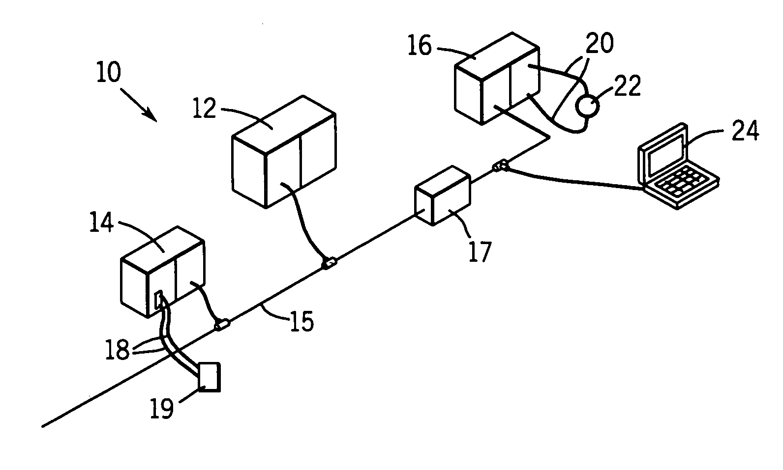
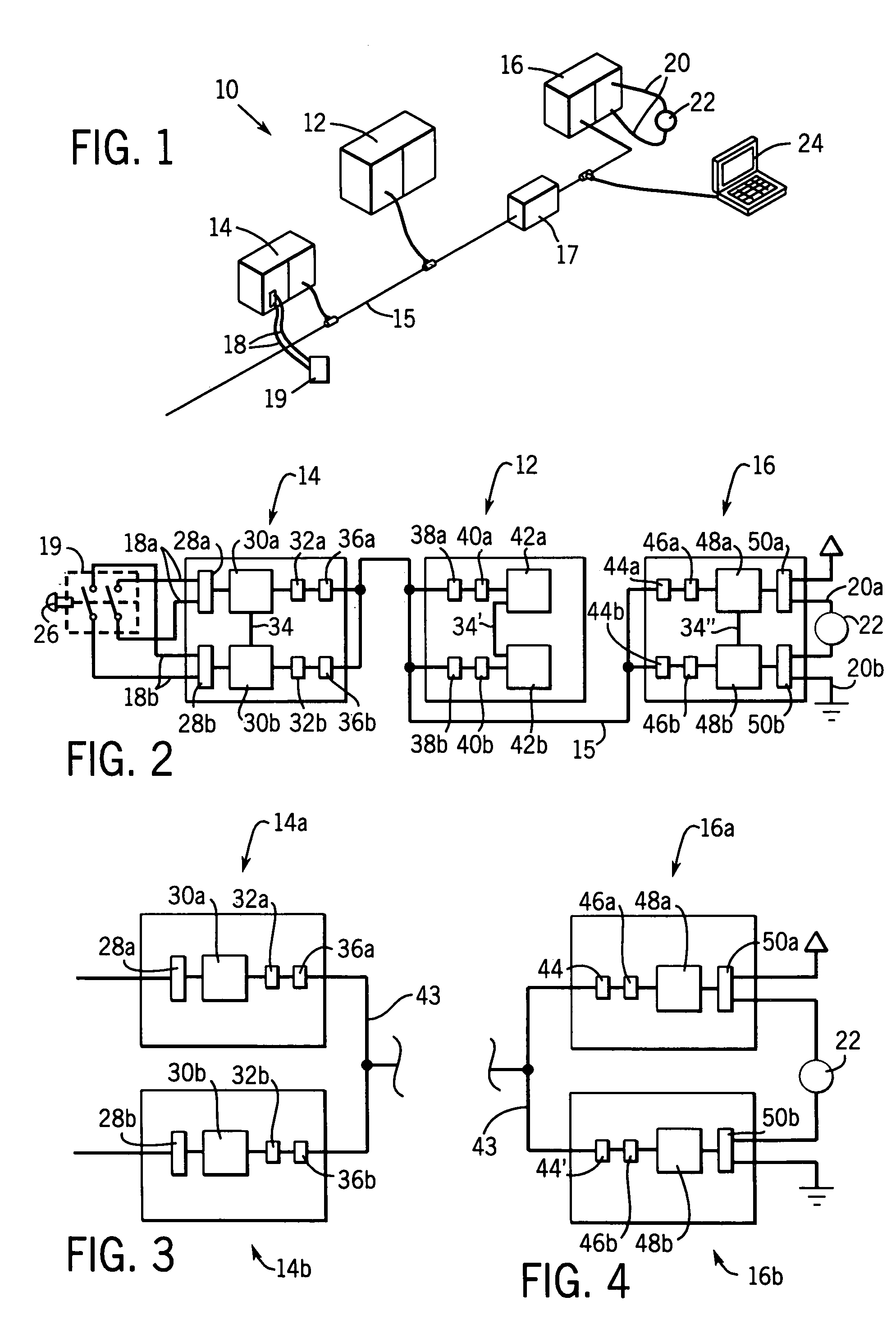
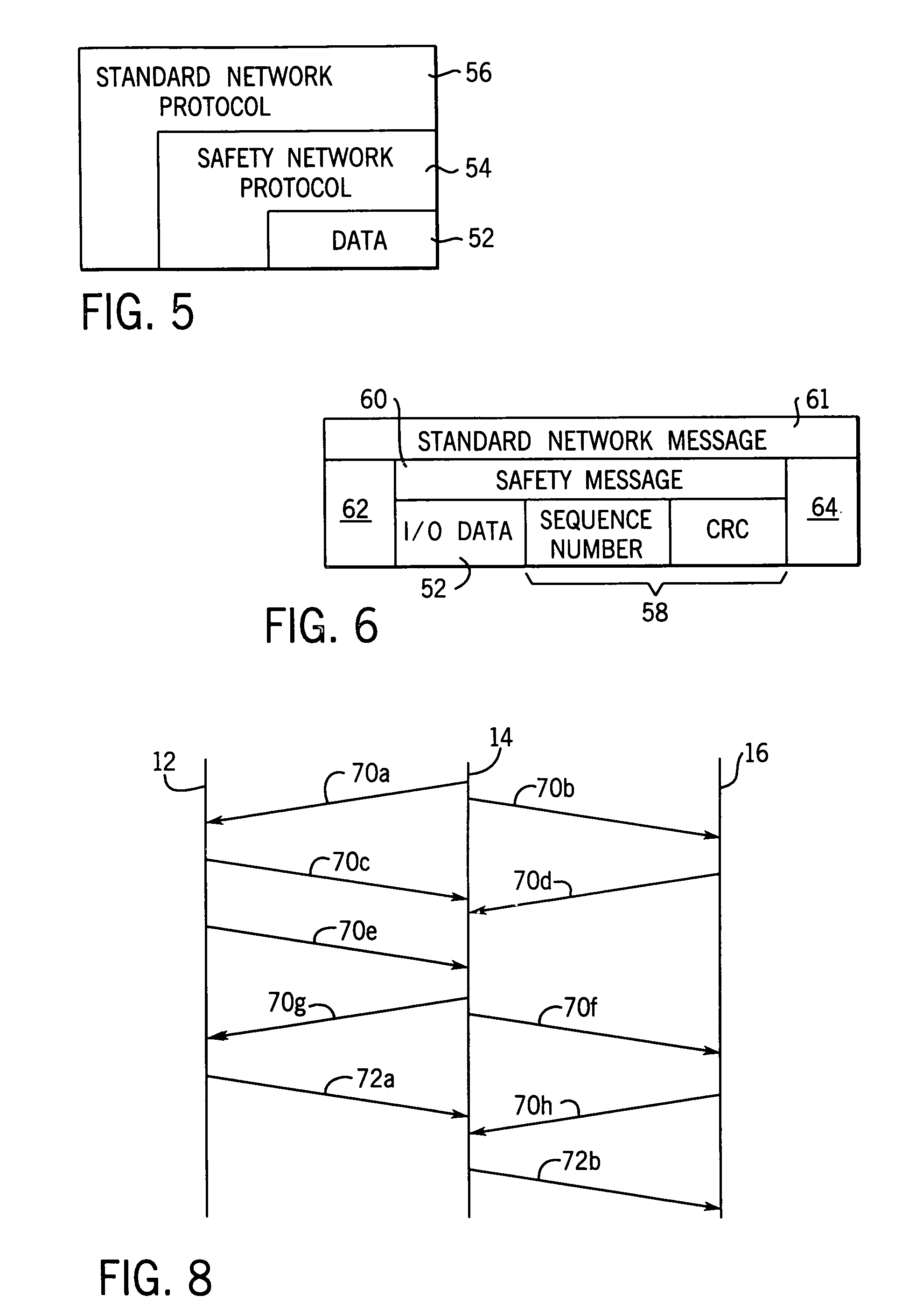
[0039]Referring now to FIG. 1, an industrial control system 10 for implementing a safety system with the present invention includes a controller 12 communicating on a serial network 15 with remote input module 14 and remote ou...


PUM


Abstract

A bridge usable in a highly reliable industrial control system provides an interface between a producer module transmitting redundant messages in accordance with a communication protocol and a consumer module receiving the messages in accordance with a different communication protocol. The bridge includes a first network interface receiving two messages from the producer, a microprocessor capable of converting the messages from the producer communication protocol to consumer communication protocol, and a second network interface transmitting the messages to the consumer. One of the messages is reversible altered with respect to the other message. The altered message is uninverted in the consumer module, and compared to the other message to ensure that no transmission errors have occurred.

Description

CROSS-REFERENCE TO RELATED APPLICATIONS[0001]Not Applicable.STATEMENT REGARDING FEDERALLY SPONSORED RESEARCH OR DEVELOPMENT[0002]Not Applicable.BACKGROUND OF THE INVENTION[0003]The present invention relates to industrial controllers used for real-time control of industrial processes, and in particular to high-reliability industrial controllers appropriate for use in devices intended to protect human life and health. “High reliability” refers generally to systems that guard against the propagation of erroneous data or signals by detecting error or fault conditions and signaling their occurrence and / or entering into a predetermined fault state. High reliability systems may be distinguished from high availability systems, however, the present invention may be useful in both such systems and therefore, as used herein, high reliability should not be considered to exclude high availability systems.[0004]Industrial controllers are special purpose computers used in controlling industrial pr...

Claims


Application Information

Patent Timeline
IPC IPC(8): G06F15/16G06F11/00G06F15/173G06F7/02H03M13/00G05B15/00G05B19/418H04L12/46H04L29/06
CPCG05B19/4185H04L1/08H04L69/08H04L1/188H04L12/462G05B2219/31122G05B2219/31244H04L1/1848H04L1/1607Y02P90/02
Inventor VASKO, DAVID A.LENNER, JOSEPH A.
Owner ROCKWELL AUTOMATION TECH
Learn More