Aircraft provided with thrust reversers

Active Publication Date: 2006-09-19
AIRBUS OPERATIONS SAS
32 Cites 7 Cited by

AI-Extracted Technical Summary

Problems solved by technology

The extra braking afforded to the brakes of an aircraft on the ground by a thrust reverser is very considerable, so that, in particular in the case of a multi-engine aircraft, the braking capacity of all the thrust reversers together is overkill.
Now, each thrust reverser exhibits a relatively considerable mass and its cost is high...

Benefits of technology

[0012]In this case, it is advantageous for said inboard engines to be prov...

Abstract

Some but not all engines of an aircraft are provided with thrust reversers. A safety device disables, at least from the position corresponding to idling, the action of the throttles corresponding to the engines devoid of thrust reversers when the thrust reversers are controlled to deployment.

Application Domain

Aircraft controlJet type power plants +4

Technology Topic

AirplaneThrottle +2

Image

  • Aircraft provided with thrust reversers
  • Aircraft provided with thrust reversers
  • Aircraft provided with thrust reversers

Examples

  • Experimental program(1)

Example

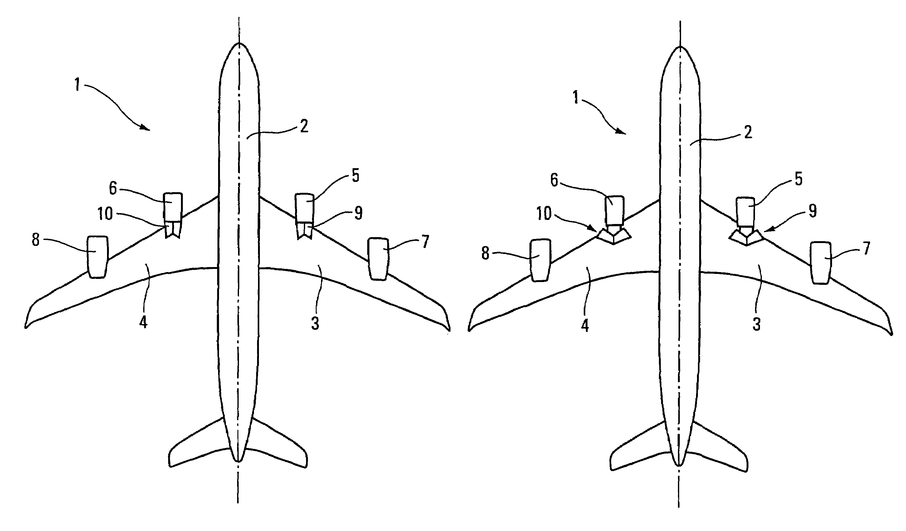
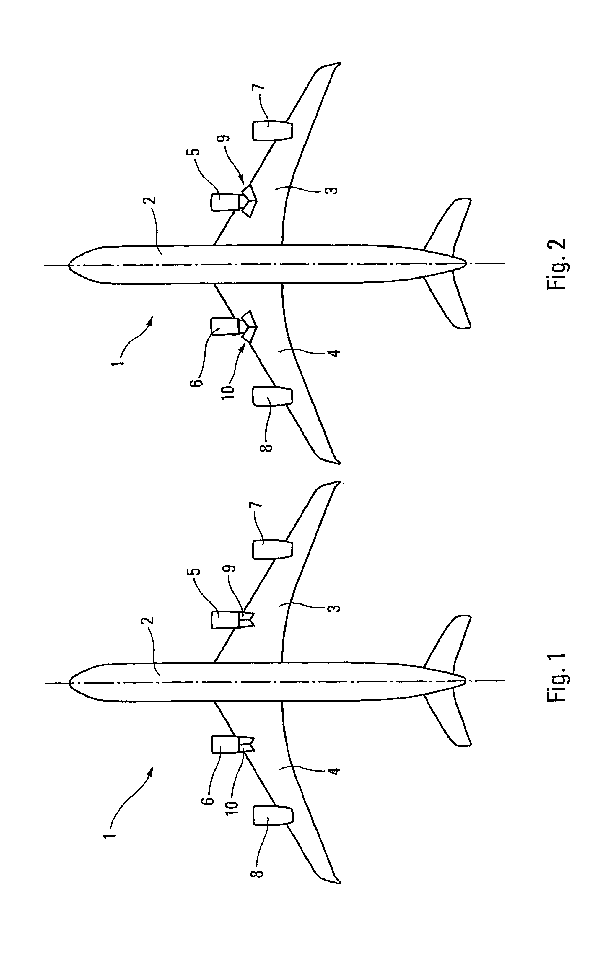
[0029]The aircraft 1, shown diagrammatically from below in FIGS. 1 and 2, comprises a fuselage 2 and two wings 3 and 4, symmetric with respect to said fuselage. On each of said wings 3 and 4 are mounted an inboard engine 5 or 6 and an outboard engine 7 or 8. The inboard engines 5 and 6 are each equipped with a thrust reverser 9 or 10, while the outboard engines 7 and 8 are devoid of such reversers. In FIGS. 1 and 2, the thrust reversers 9 and 10 have been represented in the form of rear-gate reversers but it goes without saying that they could have a different structure. The thrust reversers 9 and 10 are represented in the retracted position in FIG. 1 and in the deployed position in FIG. 2.
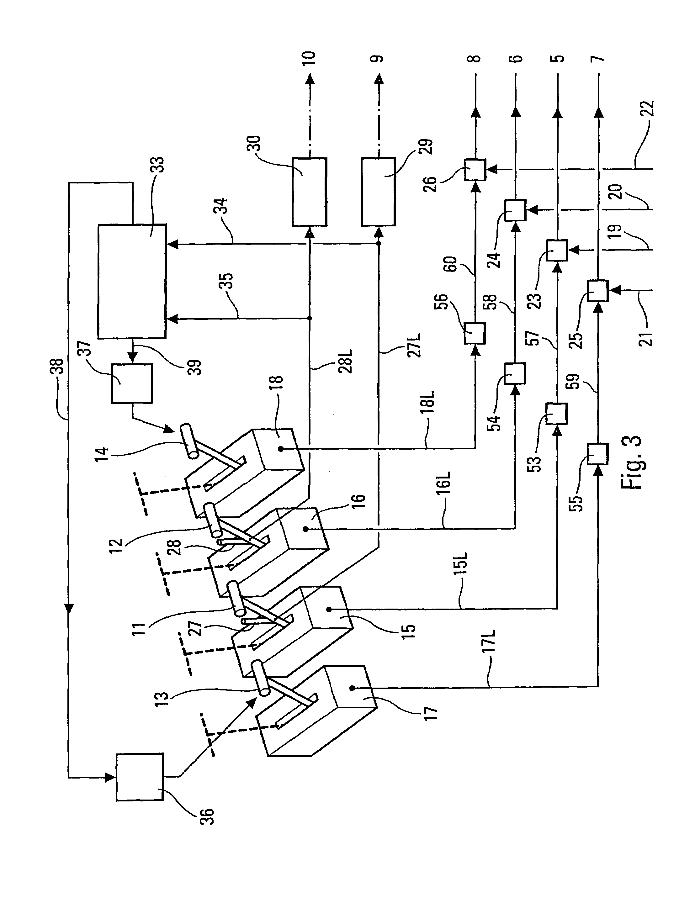
[0030]As is illustrated diagrammatically in FIGS. 3 and 4, the speed of each engine 5 to 8 is controlled by a pilot, not represented, by way of a specific throttle 11 to 14, associated with a transducer 15 to 18 delivering an electrical signal representative of the position of the corresponding throttle. Each throttle 11 to 14 can occupy any position between a position of maximum speed (represented by dashes) and an idling position (represented by a solid line).
[0031]The engines 5 to 8 are supplied with fuel by specific circuits 19 to 22, on each of which is mounted a flow rate control device 23 to 26. The flow rate control devices 23 to 26 are respectively controlled by FADEC (Full Authority Digital Engine Control) computers 53 to 56 whose output signals able to control said flow rate control devices 23 to 26 are transmitted to the latter by way of respective links 57 to 60. These FADEC computers 53 to 56 receive as input, by way of respective links 15L, 16L, 17L and 18L, the output signals from the transducers 15 to 18 which are themselves controlled by the throttles 11 to 14. Generally, the FADEC computers 53 to 56 formulate said output signals able to control the flow rate control devices 23 to 26 as a function in particular of said signals that said FADEC computers 53 to 56 receive respectively from the transducers 15 to 18. Consequently, the flow rate of fuel to the engines 5 to 8, and therefore the speed of said engines generally depends on the respective positions of the throttles 11 to 14.
[0032]Furthermore, on each of the throttles 11 and 12, respectively associated with the inboard engines 5 and 6, is mounted a member 27 or 28 able to control to deployment and to retraction the corresponding thrust reverser 9 or 10, by way of an actuation device (for example rams) 29 or 30. For this purpose, each control member 27 and 28 is able to produce, in a known manner that is not represented, a retraction electrical signal and a deployment electrical signal transmitted to the corresponding actuation device 29 or 30 by a respective link 27L or 28L.
[0033]The safety device in accordance with the present invention, represented in FIG. 3, comprises: [0034] a detector 33, receiving the retraction and deployment electrical signals flowing around the links 27L and 28L by way of links 34 and 35, respectively; and [0035] controllable latching devices 36 and 37, for example of the electromagnet type, respectively associated with the throttles 17 and 18 and controlled by the detector 33, respectively via links 38 and 39.
[0036]Thus, when all the throttles 11 to 14 are brought by a pilot into their position corresponding to the idling of the engines 5 to 8, (FIG. 3) and the control members 27 and 28 are actuated, the thrust reversers 9 and 10 deploy and this deployment is detected by the detector 33 (via the links 34, 35). The detector 33 then addresses to the latching devices 36, 37, by way of the links 38, 39, the orders to latch the throttles 13 and 14—associated with the outboard engines 7 and 8 devoid of thrust reversers—in the idling position.
[0037]As a result, as long as the thrust reversers 9 and 10 are deployed, the speed of the outboard engines 7 and 8 cannot be increased accidentally. It will be noted that the pilot nevertheless retains the possibility of dispensing with the latching exerted by the devices 36, 37 on the throttles 13, 14 by acting on these throttles with a force greater than the latching forces exerted by these devices 36, 37. This case involves an intentional action by the pilot, the aim of the present invention being to avoid unintentional actions.
[0038]On the other hand, as soon as by actuation of the control members 27 and 28 the thrust reversers 9 and 10 are controlled to retraction, the corresponding signal is detected by the detector 33 which disables the latching devices 36 and 37, the throttles 13 and 14 are then freed and it is possible to increase the throttle on the outboard engines 7 and 8.
[0039]In the variant embodiment illustrated by FIG. 4, all the elements 5 to 38 (including the links 15L, 16L, 17L, 18L, 27L and 28L) and 53 to 60 described hereinabove are found again. In this case, the detector 33 can control, by virtue of the links 38, 39, the FADEC computers 55 and 56 which respectively control the flow rate control devices 25 and 26 of the outboard engines 7 and 8, devoid of thrust reversers. When a deployment signal traverses the links 27L and 28L, the authority of the detector 33 on the FADEC computers 55 and 56 is greater than that which the throttles 13 and 14 are able to exert on these same FADEC computers. Thus, each of the engines 7 and 8 can be guaranteed to be brought to idling, even if the throttle 13 and/or the throttle 14 is not in the position corresponding to idling.
[0040]As described previously, on retraction of the thrust reversers 9 and 10, the detector 33 no longer disables the action of the throttles 13 and 14.
[0041]Represented in FIG. 5 is a more complete embodiment 43 of the detector 33, in particular in its application to the device of FIG. 4. This detector 43 is of the computer type and it can be integrated into one of the flight computers of the aircraft 1, for example a flight controls computer addressing instructions to the FADEC computers 53 to 56 providing for the command of the engines 5 to 8 of said aircraft.
[0042]The detector 43, in addition to its inputs 34 and 35 connected to the links 27L and 28L as described hereinabove, comprises: [0043] an input 44, on which appears a signal G, for example tapped off in a known manner from the landing gear, representative of the fact that the aircraft 1 is in contact with the ground; [0044] an input 45, on which appears a signal V representative of the velocity with respect to the ground of the aircraft 1; and [0045] inputs 15L, 16L, 17L and 18L on which appear signals representative of the position of the throttles 11, 12, 13 and 14, as indicated hereinabove.
[0046]Furthermore, in addition to its outputs 38 and 39, the detector 43 comprises an output 46 connected to an alarm device 47.
[0047]Thus, it is possible, for safety reasons, not to force the outboard engines 7 and 8 to idling unless the following conditions are present in isolation or in combination: [0048] the aircraft 1 is in contact with the ground; [0049] the velocity with respect to the ground of the aircraft is greater than a predetermined threshold, for example, equal to 30 knots (indeed, if the velocity of the aircraft is small, the consequences of an incident arising during the activation of the thrust reversers are also small); [0050] all the throttles 11 to 14 are in a position corresponding to idling, except possibly at least one of the two throttles 13 or 14; [0051] at least one of the thrust reversers 9 or 10 is controlled to deployment.
[0052]Furthermore, if one of the engines 7 or 8 is forced to idling, while the corresponding throttle 13 or 14 is not in a position corresponding to idling, the alarm device 47 is triggered to warn the pilot of the anomaly.
[0053]Upon the return of the thrust reversers 9 and 10 to the retracted position, it is advantageous for the detector 33 or 43 to maintain for a predetermined duration, for example equal to 30 seconds, idling on the outboard engines 7 and 8. Thus, even if the pilot unintentionally actuates the throttle 13 or 14 of one of these engines while wishing to retract the thrust reversers 9 and 10, no incident detrimental to the aircraft 1 results therefrom.

PUM

no PUM

Description & Claims & Application Information

We can also present the details of the Description, Claims and Application information to help users get a comprehensive understanding of the technical details of the patent, such as background art, summary of invention, brief description of drawings, description of embodiments, and other original content. On the other hand, users can also determine the specific scope of protection of the technology through the list of claims; as well as understand the changes in the life cycle of the technology with the presentation of the patent timeline. Login to view more.
Why Eureka
Try Eureka