Spring clamp

Inactive Publication Date: 2006-09-19
LIOU FERNG JONG
View PDF8 Cites 21 Cited by
  • Summary
  • Abstract
  • Description
  • Claims
  • Application Information

AI Technical Summary

Benefits of technology

[0005]A primary object of the present invention is to provide a spring clamp that can be conveniently operated with one finger to release two handles of the spring clamp from an immovable position when clamping two workpieces together.
[0006]Another object of the present invention is to provide a spring clamp that has simplified parts and components and can therefore be easily assembled at reduced manufacturing cost.
[0008]When the two handles are moved toward each other for the spring clamp to tightly clamp two workpieces together, an outer peripheral surface of the shaft is tightly abutted against two diametrically opposite inner walls of the through hole on the inner section of the release link, causing the two handles of the spring clamp to be immovably held in place. And, when the outer section of the release link is downward pushed with one finger, the release link is pivotally turned to separate the inner walls of the through hole on the inner section from the shaft, allowing the two handles to spring outward under a spring force of the spring clamp.

Problems solved by technology

It is somewhat troublesome and inconvenient to do so.
Moreover, the spring clamp disclosed in the above-mentioned U.S. Pat. No. 6,212,977 B1 has pretty complicate parts and components that require more time and labor to assemble and prevent the spring clamp from being manufactured at reduced cost.

Method used


Image

  • Spring clamp
  • Spring clamp
  • Spring clamp

Examples


Embodiment Construction

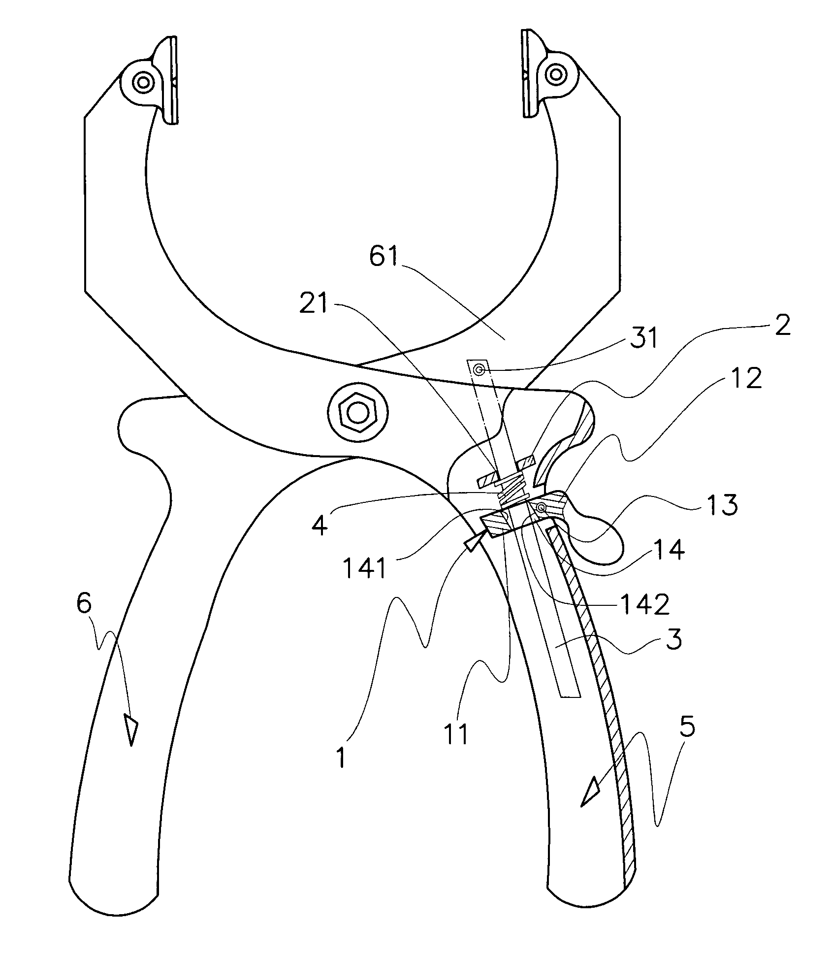
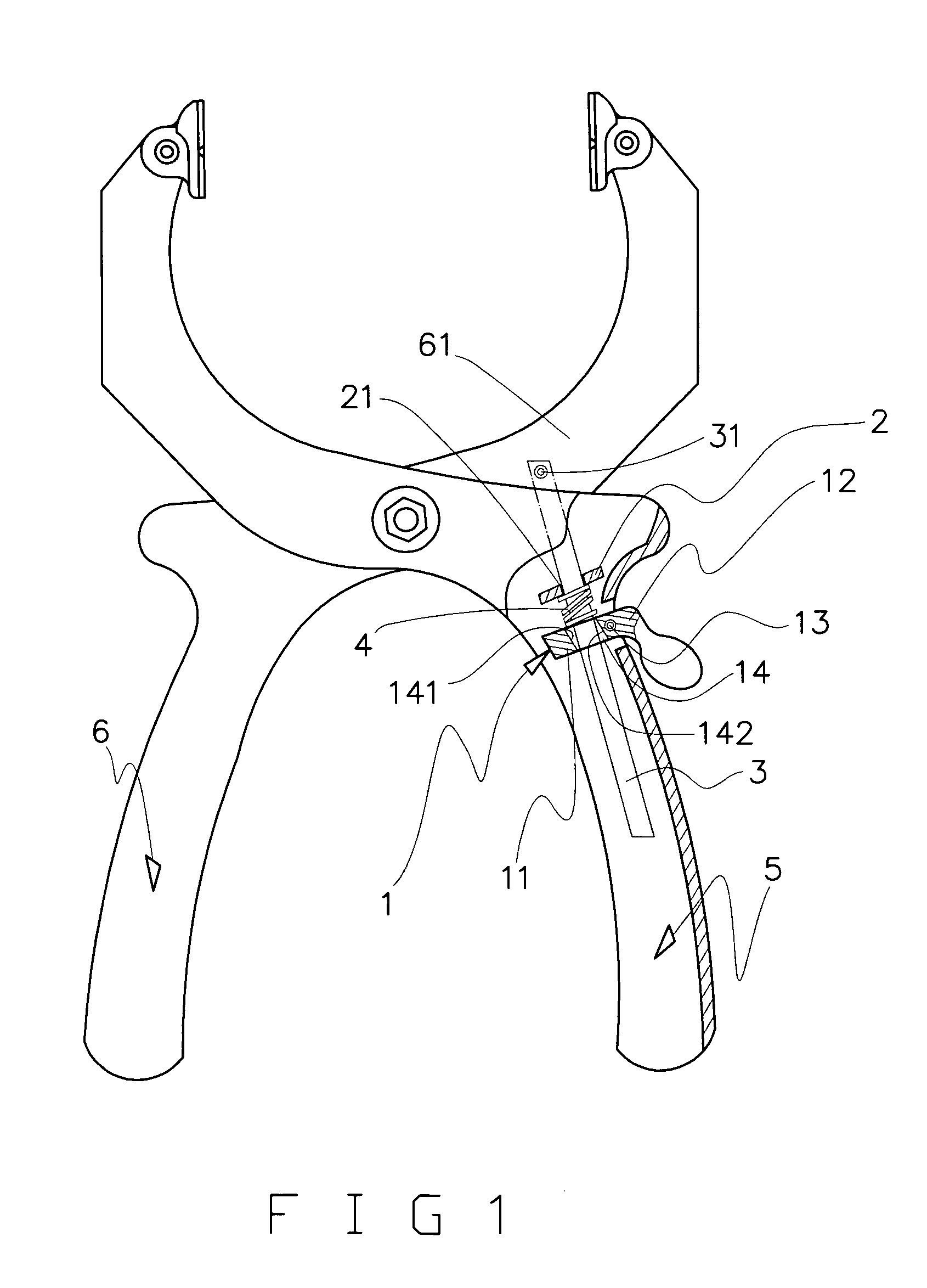
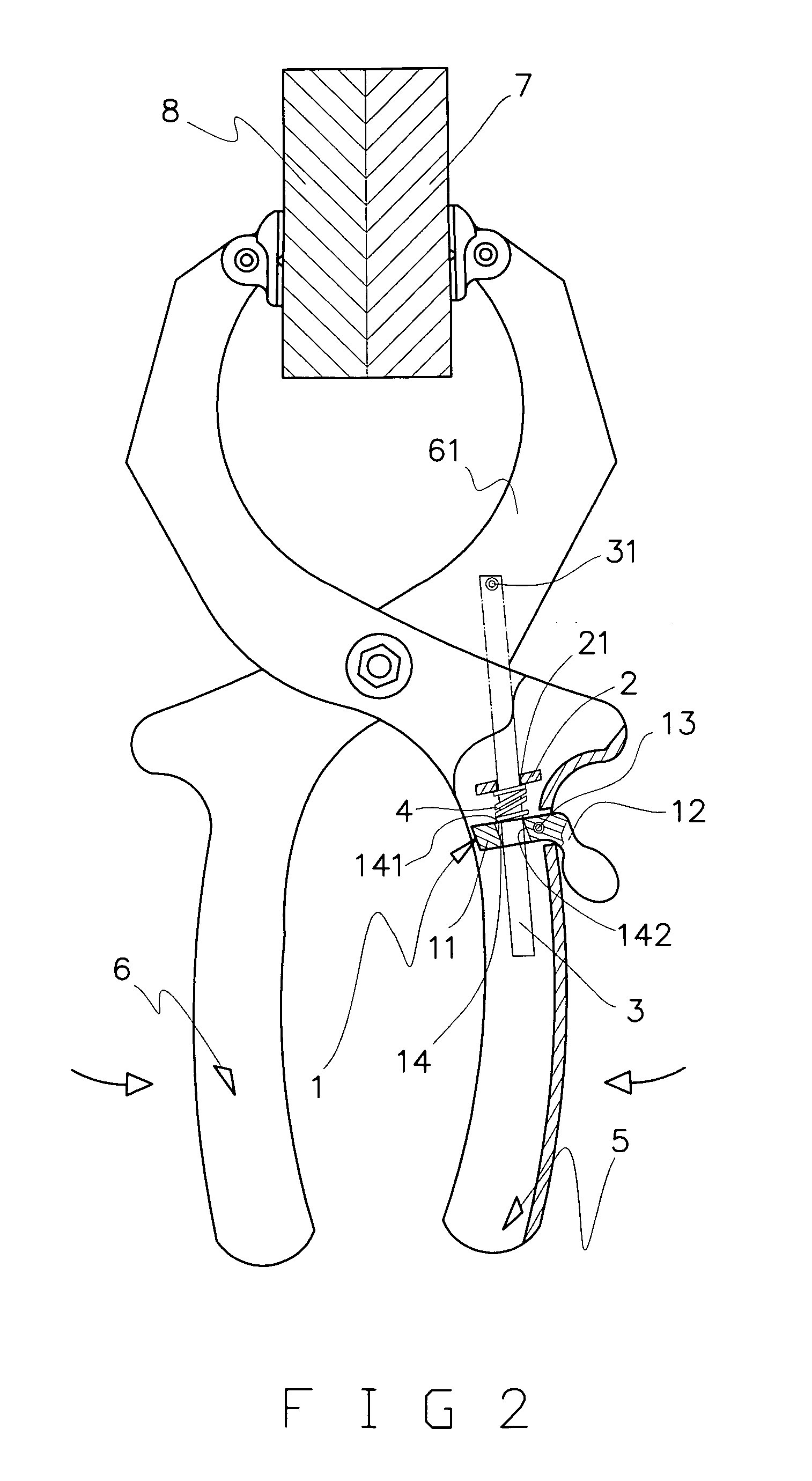
[0013]Please refer to FIG. 1 that is a partially sectioned plan view of a spring clamp according to the present invention. As shown, the spring clamp includes a first handle 5 having a release link 1 mounted thereon, and a second handle 6 being pivotally connected to the first handle 5 and having a movable jaw 61 integrally extended from a distal end thereof.

[0014]The release link 1 is a substantially L-shaped member having an inner section 11 transversely mounted in the first handle 5 and an outer section 12 located outside the first handle 5. A supporting point 13 is provided in the first handle 5 between the inner and the outer section 11, 12 of the release link 1, so that the release link 1 is pivotally turnable about the supporting point 13 when the outer section 12 is downward pushed. The outer section 12 of the release link 1 may be in the form of a lever, and is projected from a point on an outer side of the first handle 5 near a neck portion thereof. The inner section 11 of...


PUM


Abstract

A spring clamp includes a first and a second handle; a substantially L-shaped release link having an inner section transversely mounted in the first handle and an outer section located outside the first handle, and being pivotally turnably about a supporting point mounted in the first handle between the inner and the outer section of the release link; and a shaft having a front end fixedly connected to a movable jaw extended from a distal end of the second handle and a rear end obliquely extended through a hole on the inner section of the release link. To release the two handles of the spring clamp from an immovable position when clamping two workpieces together, a user needs only to downward push the outward projected outer section of the release link using one finger.

Description

FIELD OF THE INVENTION[0001]The present invention relates to a spring clamp, and more particularly to a spring clamp that can be conveniently operated to release two handles of the spring clamp from an immovable position when clamping two workpieces together simply by downward pushing a lever outward projected from an outer side of one handle of the spring clamp.BACKGROUND OF THE INVENTION[0002]A spring clamp is mainly used to tightly clamp two workpieces together for subsequent machining of the workpieces. For instance, when two pieces of wood boards are firmly clamped between two jaws of the spring clamp, it is more conveniently to perform drilling or cutting on the workpieces.[0003]U.S. Pat. No. 6,212,977 B1 granted to the same inventor of the present invention discloses a spring clamp having an auxiliary locating mechanism mounted in one handle of the spring clamp. The auxiliary locating mechanism is adapted to temporarily immovably hold the two handles of the spring clamp in pl...

Claims


Application Information

Patent Timeline
IPC IPC(8): B25B7/14B25B5/00
CPCB25B7/14B25B5/06
Inventor LIOU, FERNG-JONG
Owner LIOU FERNG JONG
Why Eureka
Try Eureka