Flow-restricted printing cylinder for a removable printing sleeve

a printing cylinder and printing sleeve technology, which is applied in the direction of printing, rotary lithographic machines, shafts and bearings, etc., can solve the problems of inflating or expanding, affecting and affecting the flow of the printing cylinder. achieve the effect of improving the fluid-assisted removal or placement of the printing sleev

Inactive Publication Date: 2006-09-19
GOSS INT AMERICAS
View PDF21 Cites 19 Cited by
  • Summary
  • Abstract
  • Description
  • Claims
  • Application Information

AI Technical Summary

Benefits of technology

[0009]An object of the present invention is to provide a printing cylinder that can accommodate the fluid-assisted removal or placement of more than one printing sleeve. An alternate or additional object of the present invention is to improve the fluid-assisted removal or placement of a printing sleeve.

Problems solved by technology

However, blankets can become stuck when mounted for too long, as air pressure from the air holes can be blocked and not reach the gear side end of the cylinder.
Moreover, the use of only one set of air holes on the work side end makes hole placement critical, or the sleeve will not inflate or expand at all.
With improperly placed holes, the air may simply rush out of the work side end without inflating the gear side end.
A single set of work side holes can inflate only one of the blankets at the work side, thus not permitting the other blankets closer to the gear side to be removed.
A large pressure reduction results as the air rushes out the uncovered holes and the flow drops at the work side holes, thus making blanket placement or removal difficult or impossible.
These features tend to be expensive and are complicated, especially because the cylinder must rotate.

Method used


Image

  • Flow-restricted printing cylinder for a removable printing sleeve
  • Flow-restricted printing cylinder for a removable printing sleeve
  • Flow-restricted printing cylinder for a removable printing sleeve

Examples


Embodiment Construction

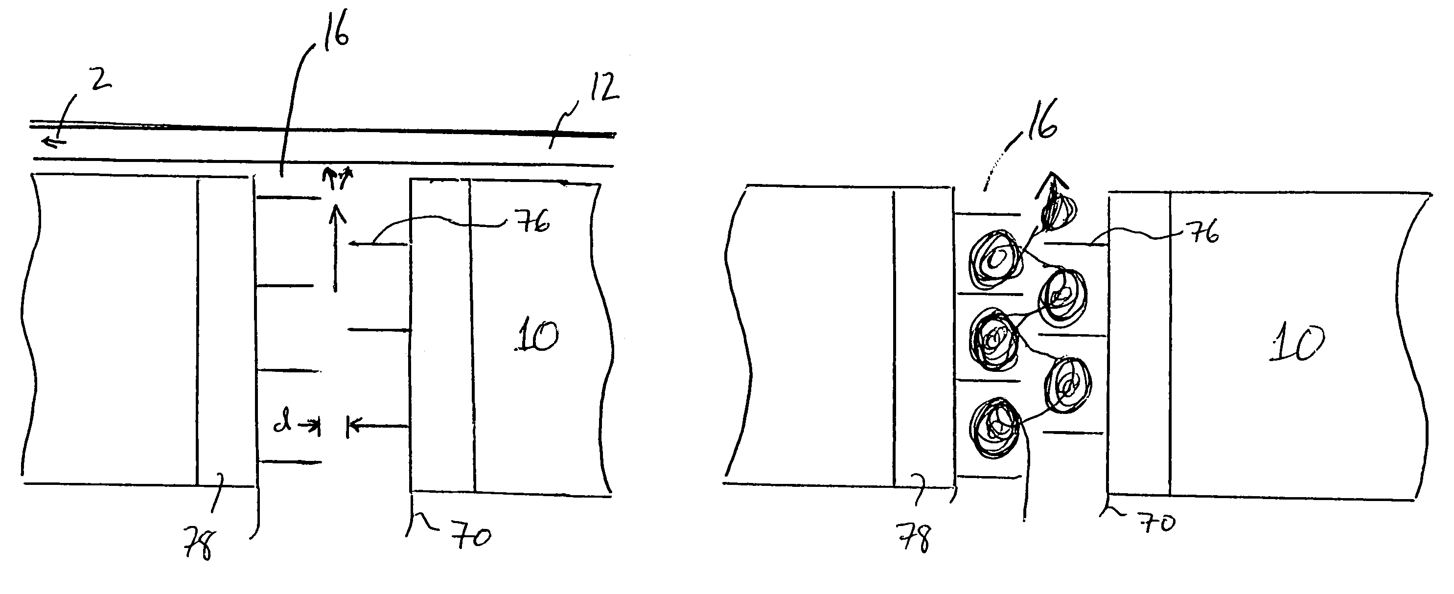
[0030]FIG. 1 shows schematically a gear side view of a lithographic offset printing press 1 according to the present invention. A web 5 passes between a nip formed by a first sleeve-shaped blanket 12 and a second sleeve-shaped blanket 62, and then through a second nip formed by a third sleeve-shaped blanket 112 and a fourth sleeve-shaped blanket 162. Blanket 12 is mounted axially on a blanket cylinder 10 having flow restrictors, as will be described with respect to FIG. 2, and blanket 62 is mounted axially on a similar blanket cylinder 59. Plate cylinders 8, 58 contact blankets 12, 62, respectively, to provide an inked image to the blankets, the image then being transferred to the web 5.

[0031]The blankets 12, 62, 112, 162 are axially removable through openings in the work side frame of the printing press 1, with the aid of air pressure supplied through holes in the blanket cylinders 10, 60, 110, 160, respectively. A compressor 80 feeds air through a feed line 90 to the blanket cylin...


PUM


Abstract

A printing cylinder for accepting an axially-removable printing sleeve includes a cylinder body having an outer surface, the outer surface having at least one hole and a supply line in the cylinder body for supplying fluid to the at least one hole. The supply line has at least one flow restrictor designed to alter fluid flow as a function of the at least one hole being covered by an axially-removable printing sleeve. Also provided is a printing press having two such cylinders and a common pressure source. A method for axially removing a printing sleeve over a printing cylinder includes the steps of applying fluid pressure to an inside of a printing sleeve located on a printing cylinder through holes at a work side end of the printing cylinder and through other holes between the holes at the work side end and a gear side end of the printing cylinder, sliding the printing sleeve in a direction of the work side end of the printing cylinder, and automatically restricting flow through the other holes when the printing sleeve no longer is located over the other holes.

Description

BACKGROUND INFORMATION[0001]1. Field of the Invention[0002]The present invention relates generally to printing presses and more particularly to printing presses having printing sleeves that are placed on or removed from a cylinder with the aid of air or other fluid pressure.[0003]2. Background of the Invention[0004]Tubular-shaped printing sleeves, such as offset lithographic printing blankets described in U.S. Pat. No. 5,215,013, are placed and removed axially over a printing cylinder. As described with respect to a blanket in the '013 patent, air holes typically are located on a work side end of the blanket cylinder to provide pressure to the inside of the blanket as the blanket is removed or placed axially over the blanket cylinder.[0005]However, blankets can become stuck when mounted for too long, as air pressure from the air holes can be blocked and not reach the gear side end of the cylinder. Moreover, the use of only one set of air holes on the work side end makes hole placeme...

Claims


Application Information

Patent Timeline
Patent Type & Authority Patents(United States)
IPC IPC(8): B41F33/00B41F30/00B41F7/02B41F7/12B41F30/04F16C13/00
CPCB41F30/04B41P2227/20
Inventor VROTACOE, JAMES BRIAN
Owner GOSS INT AMERICAS
Why Eureka
Try Eureka