Locking mechanism for folding legs

a locking mechanism and folding leg technology, applied in the field of folding support legs, can solve the problems of affecting the stability of the support surface, the strength of the prior leg locking mechanism is relatively low, and the legs and the support surface are easily collapsed, so as to achieve the effect of simple construction and operation

Inactive Publication Date: 2006-09-19
MITY-LITE
View PDF22 Cites 24 Cited by
  • Summary
  • Abstract
  • Description
  • Claims
  • Application Information

AI Technical Summary

Benefits of technology

[0007]It has been recognized that it would be advantageous to develop a locking mechanism for folding legs which is strong and durable, simple in construction and operation, and is relatively lightweight.
[0008]It has also been recognized that it would be advantageous to provide a locking mechanism for folding legs which eliminates or reduces potential hazards to one's knees, and which also provides for a wide range of leg styles.
[0010]In accordance with a more detailed aspect of the present invention, the locking mechanism may include a pair of oppositely oriented bases attached to the support surface, each having a support leg connected thereto, and the pair of support legs being mechanically connected, the selectively releasable engagement mechanism further comprising an oppositely directed spring force built into each of the connected pair of legs, such that the natural position of the legs provides force to engage the teeth. A flexible tension member may be provided for countering the force of the engaging means to allow the tops of the legs to be drawn together, thus drawing the teeth out of engagement, allowing the legs to be rotated from the extended position to the folded position, and vice versa.

Problems solved by technology

Unfortunately, some prior leg locking mechanisms have relatively low strength, and are susceptible to failure.
For example, hinged angular supports can easily buckle if a locking collar is not properly placed, possibly resulting in collapse of the legs and the support surface.
Others are complicated, expensive, and sometimes not very durable.
Many of them are also quite heavy, and noisy, thus reducing the desirability, portability, and practicality of the support device.

Method used


Image

  • Locking mechanism for folding legs
  • Locking mechanism for folding legs
  • Locking mechanism for folding legs

Examples


Embodiment Construction

[0032]For the purposes of promoting an understanding of the principles of the invention, reference will now be made to the exemplary embodiments illustrated in the drawings, and specific language will be used to describe the same. It will nevertheless be understood that no limitation of the scope of the invention is thereby intended. Any alterations and further modifications of the inventive features illustrated herein, and any additional applications of the principles of the invention as illustrated herein, which would occur to one skilled in the relevant art and having possession of this disclosure, are to be considered within the scope of the invention.

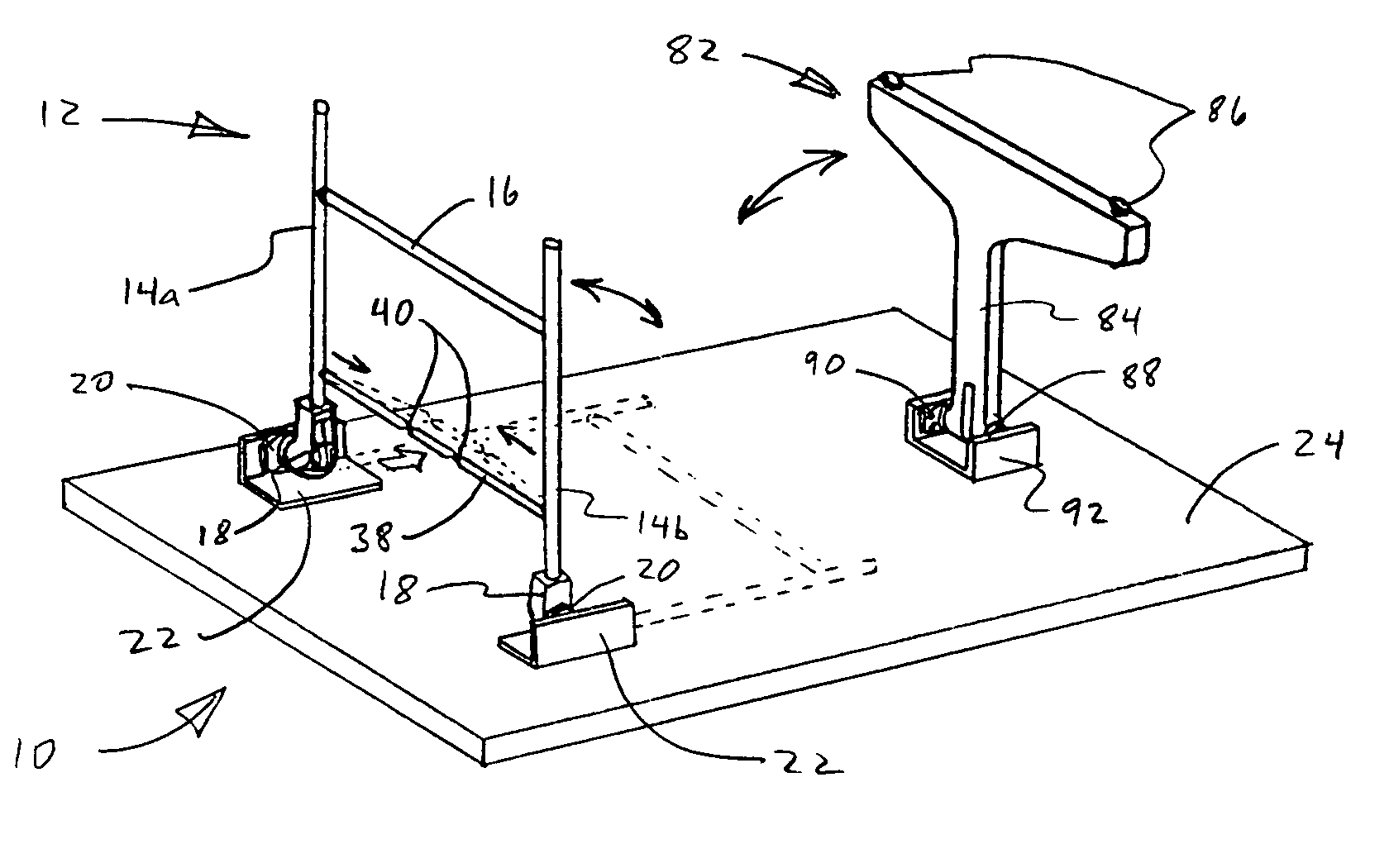
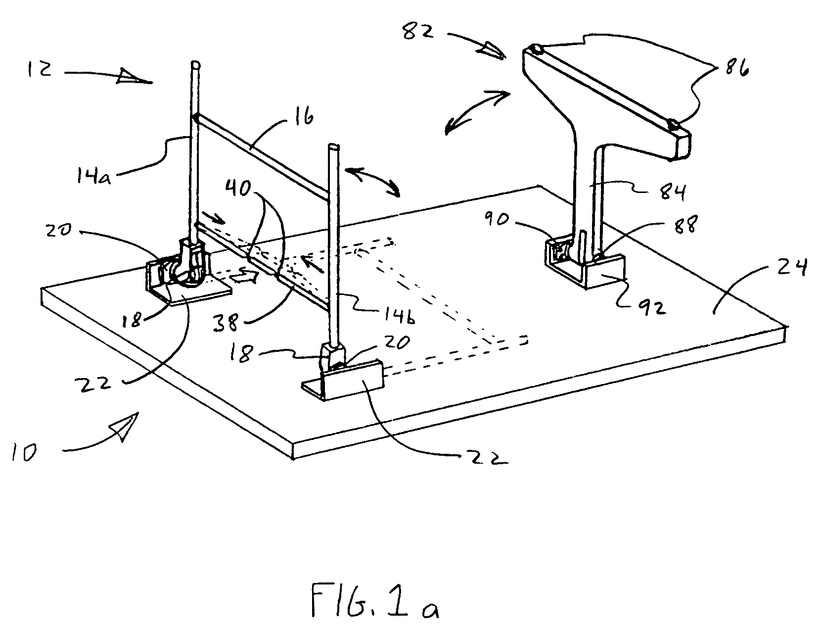
[0033]Viewing FIG. 1A, the invention is shown in use with a table 10, which is shown inverted for clarity. It will be apparent that the present invention is suitable for use with a wide variety of items other than tables, such as chairs, portable stage platforms, risers, and any other support surface requiring foldable support legs...


PUM


Abstract

A locking mechanism for a support leg hingedly attached to a support surface includes a base, attached to the support surface, with a plurality of angularly spaced, radial teeth, and a coupler, attached to the support leg, having a plurality of angularly spaced, radial teeth configured to mate with the teeth of the base. A selectively releasable engagement mechanism is configured to engage and disengage the teeth of the base with the teeth of the coupler, to allow selective rotation of the support leg between an extended position and a folded position, and to lock the leg in the extended or folded position.

Description

[0001]This application is a continuation-in-part of U.S. patent application Ser. No. 09 / 859,919 filed on May 17, 2001 entitled LOCKING MECHANISM FOR FOLDING LEGS, now U.S. Pat. No. 6,598,544 which issued on Jul. 29, 2003.BACKGROUND OF THE INVENTION[0002]1. Field of the Invention[0003]This invention relates to foldable support legs for tables, chairs, portable staging, risers, or other similar portable equipment requiring foldable legs for supporting a surface. More particularly, the present invention relates to an improved locking mechanism for folding legs which is simpler and stronger than other similar mechanisms.[0004]2. Related Art[0005]Portable tables, chairs, risers, etc. having foldable legs are well known. Such devices typically comprise a support surface of some kind having a plurality of support legs hingedly attached to the underside. The legs are rotatable from a folded position against the underside of the support surface, to an extended position where they are general...

Claims


Application Information

Patent Timeline
Patent Type & Authority Patents(United States)
IPC IPC(8): A47B3/00
CPCA47B3/0815A47B3/0812
Inventor LAWS, DAVID J.SPENDLOVE, DALESMITH, RICHARD D.SWINDLER, PHILLIP J.
Owner MITY-LITE
Why Eureka
Try Eureka