Method and apparatus for calibration of indirect measurement systems

a technology of indirect measurement and calibration method, which is applied in the direction of calibration apparatus, instruments, heat measurement, etc., can solve the problems of complex relationship between the thickness of solder and the gray value observed in cross-sectional or transmission images, difficult to model accurately, and use of broadband (typically bremsstrahlung) x-ray sources in conjunction with monochromatic detectors, etc., to achieve a high degree of portability and accuracy, the effect of minimizing the differences between the local

Inactive Publication Date: 2006-09-19
AGILENT TECH INC
View PDF6 Cites 17 Cited by
  • Summary
  • Abstract
  • Description
  • Claims
  • Application Information

AI Technical Summary

Benefits of technology

[0011]Each one or more non-reference indirect measurement systems are also provided with a correction function fitting procedure that generates a correction function, g(M), that corrects any measurement, M, to its corrected value MC to minimize differences between the local system and the reference system. In particular, the correction function fitting procedure obtains measurement values from a small number of calibration samples measured on the particular non-reference indirect measurement system. The correction function fitting procedure fits these obtained measurement values to corresponding known reference values that are associated with each of the calibration samples and are measured on or simulated for the reference indirect measurement system to generate a correction function. Preferably, the correction function fitting procedure fits the calibration sample points to a line / linear function, a low order polynomial, or other parametric function characterized by a small number of parameters to generate the correction function, g(M). Non-reference indirect measurement systems may then be corrected quickly and accurately to match the results that would have been obtained had the reference indirect measurement system made the same measurements, thereby generating a high degree of portability and accuracy.

Problems solved by technology

Unfortunately, the relationship between solder thickness and the gray value observed in cross-sectional or transmission images is complex and difficult to model accurately.
Additional problems arise from the use of broadband (typically bremsstrahlung) x-ray sources in conjunction with monochromatic detectors.
Monochromatic detectors sense only the integrated intensity reaching the detector, so it is typically not possible to unambiguously recover the thickness of the intervening materials.
Calibration in such indirect-sensing systems is often expensive, time-consuming, and error prone.
A number of disadvantages, representative of indirect measuring systems, are apparent in the above example.
A large number of calibration samples may be required, resulting in large expenses.
Additionally, measuring many samples accurately is time consuming, reducing system availability for normal use.
Fabrication of the calibration samples can pose its own challenges.
As a result, strips whose thickness is controlled to the desired accuracy are not readily available commercially.
However, mechanical measurement can alter solder strip thickness.
Thickness measurements may suffer from portability and accuracy problems as a result.
Finally, the need to minimize the time that the system is unavailable for production use limits the sophistication of the fitting procedure used to describe the relationship between measured gray values and solder thickness.

Method used


Image

  • Method and apparatus for calibration of indirect measurement systems
  • Method and apparatus for calibration of indirect measurement systems
  • Method and apparatus for calibration of indirect measurement systems

Examples


first embodiment

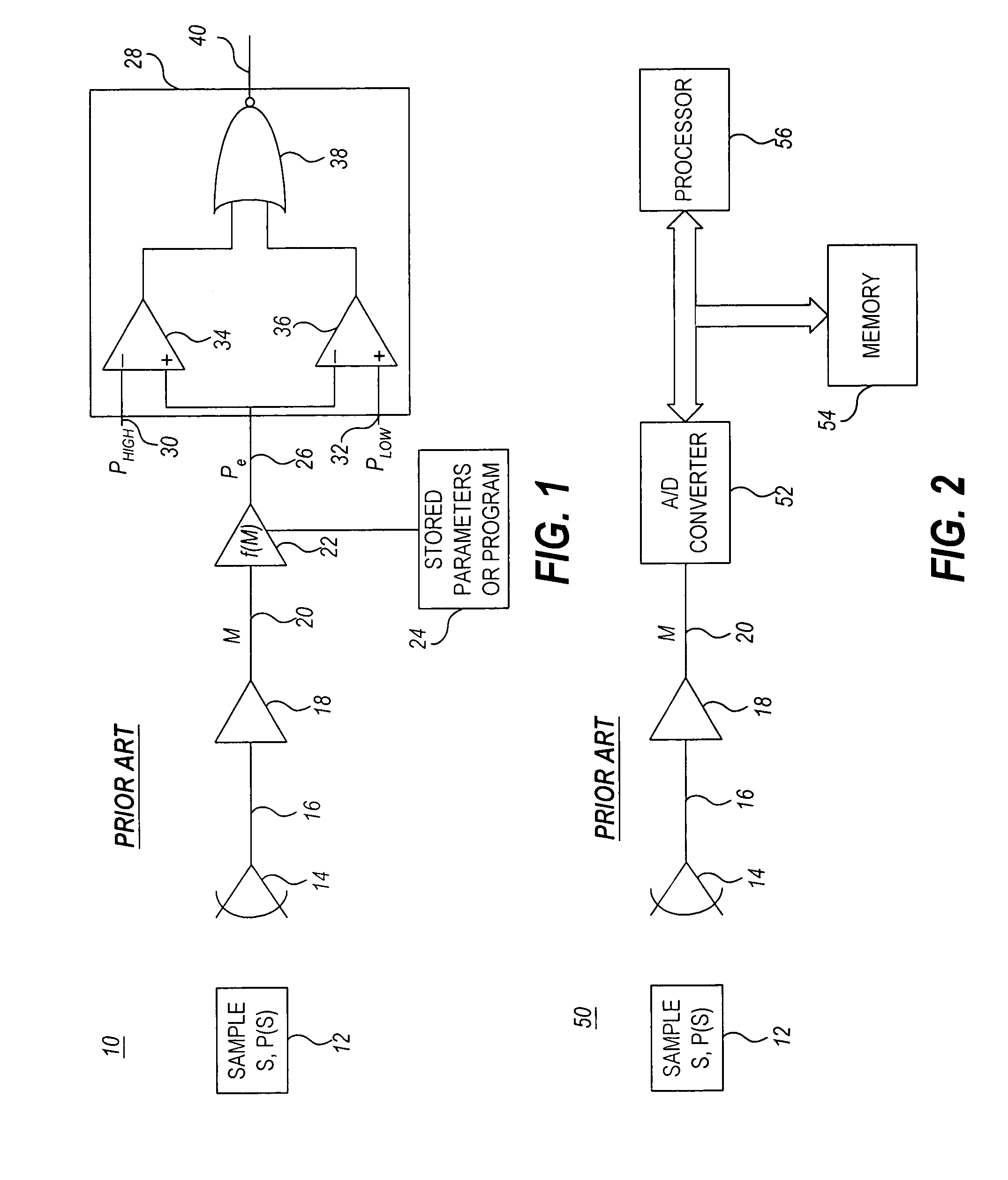
[0043]Turning now to the drawings, FIG. 1 is a simplified schematic block diagram of a prior art indirect measurement system 10. As illustrated, system 10 includes one or more sensors 14 which generate a sensed signal 16 that feeds a buffer / amplifier 18. The output 20 of the buffer / amplifier 18 is input to a map function 22. The map function 22 may be implemented as program instructions stored in memory 24 and executed by a processor (not shown). The map function 22 may be algorithmic, actively calculating an estimated parameter value, Pe, for each measurement value, M, or alternatively, estimated parameter values for given measurement values may be stored in memory, for example in a look-up table. The parameters and / or algorithms which need to be stored can reside in computer memory, in analog hardware (e.g. in settings of potentiometers or choice of component values), or in algorithmic form (e.g. executable code residing in firmware or software. The output 26 of the map function 2...

second embodiment

[0045]Similarly, the measurement 20, M, may be digitized and some or all subsequent operations performed digitally rather than in analog circuitry, as illustrated in the system 50 in FIG. 2, which shows a prior art indirect measurement system. Analog-to-digital (A / D) converter 52 converts the analog measurement 20, M, to a digital signal, which is processed by a digital map function under the control of a processor 56. In this embodiment, the map function, f(M), is stored in memory 54 along with any other algorithms and data required for system operation.

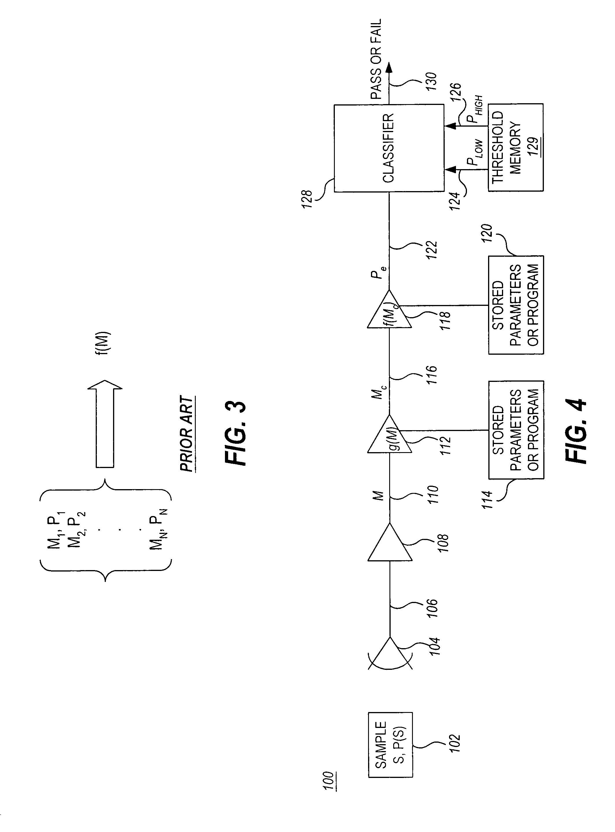
[0046]As described above, indirect measurement systems have conventionally been calibrated by measuring a large number, N, of calibration samples, {Si} at points, {Mi, Pi}, where i=1, . . . N, which are used to construct a new estimate of f(M), or to improve an existing estimate, as illustrated schematically in FIG. 3. Here Mi denotes the measurement obtained for the ith sample, Si, having known value, Pi, of the physical parameter ...


PUM

PropertyMeasurementUnit
thicknessesaaaaaaaaaa
thicknessaaaaaaaaaa

Abstract

A calibration technique is presented for calibrating non-reference indirect measurement systems with respect to a reference indirect measurement system. A reference map function filling procedure fits a reference map function based on known values of a parameter of interest associated with reference calibration samples and corresponding reference values associated with the reference calibration samples. A correction function fining procedure fits a correction function based on reference values for calibration samples measured on or simulated for the reference indirect measurement system and corresponding values measured on the non-reference indirect measurement system. During normal use, the non-reference indirect measurement system obtains measurements, corrects the measurements using the correction function, and estimates the parameter of interest of the object of interest using the reference map function based on the corrected measurements.

Description

BACKGROUND OF THE INVENTION[0001]The present invention relates generally to instrument calibration and more particularly to a novel method and apparatus for calibration of indirect measurement and inspection systems.[0002]Inspection and measurement systems often depend on accurately sensing one or more physical parameters reflecting a process of interest. In electronics, for example, automated test equipment (ATE) may, in various situations, be required to accurately measure voltage, current, resistance, or phase. In radiation dosimetry, systems may be required to accurately measure total accumulated dose or radiation level. Similarly, systems may be required to measure length, time, mass, or any of a variety of physical parameters. It is generally desirable that the measured result be repeatable, portable, and accurate. Repeatability means that multiple consecutive readings of the same parameter on a single system give the same result within the required tolerance. Repeatability is...

Claims


Application Information

Patent Timeline
Patent Type & Authority Patents(United States)
IPC IPC(8): G01D18/00G01N23/06G01K7/16G06F15/00
CPCG01D3/022A61B6/583
Inventor HEUMANN, JOHN M.ACOSTA, EDUARDO
Owner AGILENT TECH INC
Why Eureka
Try Eureka