
Transponder, interrogator, and communication system

Active Publication Date: 2006-09-19
BROTHER KOGYO KK
View PDF17 Cites 19 Cited by
  • Summary
  • Abstract
  • Description
  • Claims
  • Application Information

AI Technical Summary

Benefits of technology

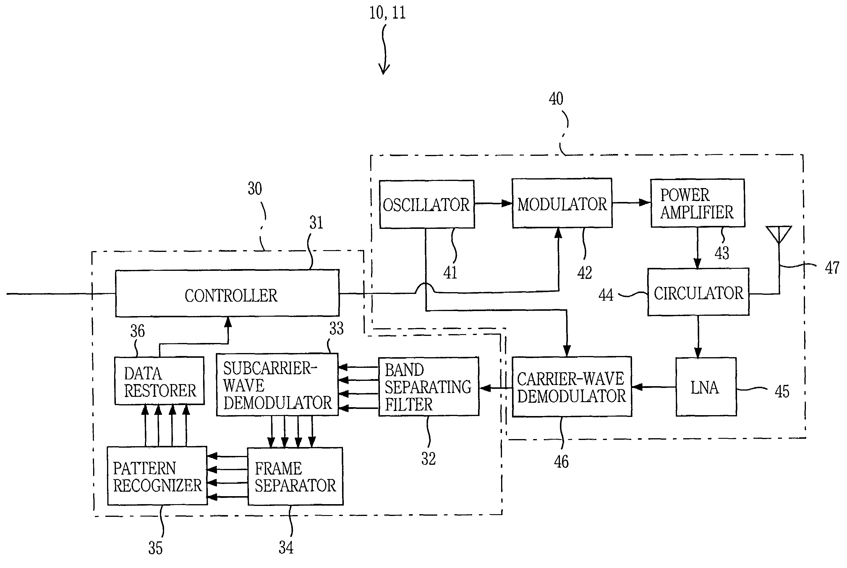
[0008]According to the mode (1), the first portion of the information signal may be the entirety of the information signal. For example, in the case where the information signal comprises an identification (ID) code of the transponder, and transmission data or information to be transmitted from the transponder to the interrogator, the first portion of the information signal may comprise at least one of the transponder's ID code and the transmission information. Thus, the unit data represented by the frequency hopping pattern may comprise at least one of the transponder's ID code and the transmission information. However, the frequency hopping pattern may represent, in addition to the unit data comprising the transmission information as part of the first portion, a portion, or the entirety, of the transponder's ID code as another part of the first portion. Even in the case where a plurality of transponders simultaneously return, to an interrogator, respective reflected waves that have been modulated based on respective subcarrier waves modified according to respective frequency hopping patterns, the interrogator can simultaneously distinguish the respective reflected waves returned from the transponders from each other based on the respective frequency hopping patterns. In addition, the probability that those reflected waves interfere with each other is very small. Therefore, the transponders need not return the respective reflected waves at respective different timings to avoid the interference of the reflected waves. In addition, the interrogator need not control the transponders about their reflected-wave returning operations. For example, the interrogator need to control a transponder to stop its reflected-wave returning operation after the interrogator has received the reflected wave returned from the specific transponder, or need not control a specific transponder to start its reflected-wave returning operation after the interrogator designates an ID code of the specific transponder. Moreover, since the interrogator can obtain the unit data from the frequency hopping pattern, the interrogator can easily correct possible errors of the data and restore the data to its original state.
[0049]According to this mode (22), the interrogator can reliably distinguish the reflected wave returned from the transponder, from another or other reflected waves returned from another or other transponders.

Problems solved by technology

In addition, the probability that those reflected waves interfere with each other is very small.

Method used


Image

  • Transponder, interrogator, and communication system
  • Transponder, interrogator, and communication system
  • Transponder, interrogator, and communication system

Examples


Embodiment Construction

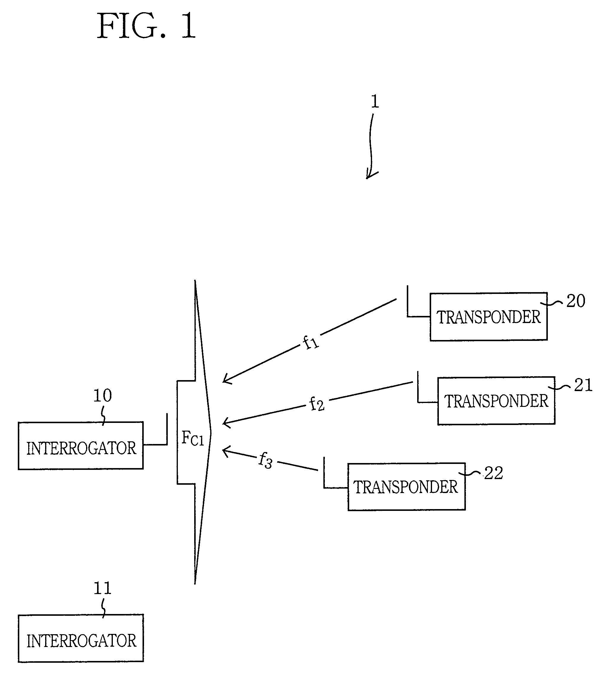
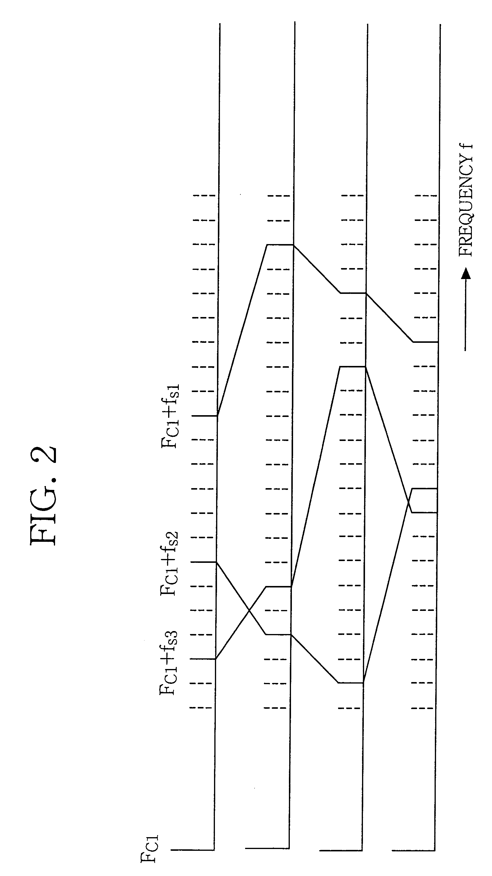
[0073]Hereinafter, there will be described a wireless communication system 1 embodying the present invention, by reference to the drawings. FIG. 1 shows an arrangement of the communication system 1; and FIG. 2 shows a relationship between a carrier wave and reflected waves that is used in the communication system 1.

[0074]As shown in FIG. 1, the communication system 1 includes two interrogators 10, 11 and three transponders 20, 21, 22. The interrogator 10 transmits a carrier wave, FC1, to each of the transponders 20–22. The transponder 20 returns a reflected wave, f1, to the interrogator 10; and the other transponders 21, 22 return respective reflected waves, f2, f3, to the same 10. The following descriptions of the interrogator 10 also apply to the interrogator 11.

[0075]More specifically described, the three transponders 20–22 subject respective received carrier waves FC1 to respective secondary modulations using respective subcarrier waves, fs1, fs2, fs3, that have been subjected t...


PUM


Abstract

A communication system 1 includes interrogators 10, 11 and transponders 20, 21, 22. The interrogator 10 transmits a carrier wave, FC1, to the transponders 20, 21, 22, and the transponders 20, 21, 22 return respective reflected waves, f1, f2, and f3, to the interrogator 10. The transponders 20, 21, 22 modulate the received carrier waves FC1 using respective subcarrier waves that have been modulated using respective information signals, and return the thus modulated carrier waves as the reflected waves f1, f2, and f3 to the interrogator 10. The transponders 20, 21, 22 hop the frequencies of the subcarrier waves according to respective different hopping patterns, such that an initial hopping frequency with which each of the frequency hopping patterns begins represents right-hand two bit values of a four-bit identification code of a corresponding one of the transponders 20, 21, 22, and respective hopping frequencies of the each frequency hopping pattern represent respective bit values of four-bit transmission data transmitted from the corresponding transponder 20, 21, 22 to the interrogator 10.

Description

BACKGROUND OF THE INVENTION[0001]1. Field of the Invention[0002]The present invention relates to a transponder, an interrogator, and a communication system in which an interrogator transmits a carrier wave to a transponder and the transponder receives the carrier wave, modulates the received carrier wave, and returns the modulated carrier wave as a reflected wave to the interrogator.[0003]2. Discussion of Related Art[0004]Japanese Patent Publication No. 2000-49656 or its corresponding U.S. Pat. No. 6,177,861 discloses a wireless communication system including a plurality of transponders and an interrogator that transmits a carrier wave to the transponders so that each of the transponders modulates the carrier wave using an information signal such as an identification (ID) signal identifying the each transponder, or using a subcarrier wave that has been modulated using the information signal, and returns the modulated carrier wave as a reflected wave to the interrogator.[0005]However...

Claims


Application Information

Patent Timeline
IPC IPC(8): H04Q7/00H04B1/38H04L7/00G06K19/07H04B1/59H04B1/713
CPCG06K19/0723
Inventor TAKI, KAZUNARIOHASHI, TSUYOSHINAGAI, TAKUYA
Owner BROTHER KOGYO KK
Learn More