Method and device for cooling and electrically insulating a high-voltage, heat-generating component such as an x-ray tube for analyzing fluid streams

a technology of heat-generating components and x-ray tubes, which is applied in the direction of insulated conductors, cables, instruments, etc., can solve the problems of stringent control conditions, limited detection of sulfur concentrations in fuels, and existing xrf methods

Inactive Publication Date: 2006-09-19
S RAY OPTICAL SYST
View PDF15 Cites 91 Cited by
  • Summary
  • Abstract
  • Description
  • Claims
  • Application Information

AI Technical Summary

Benefits of technology

[0022]A further aspect of the present invention is an x-ray fluorescence analysis system, comprising: an x-ray source assembly having an x-ray source and a housing; a first x-ray focusing device operatively connected to the x-ray source assembly and having means for aligning the first x-ray focusing device with the x-ray source assembly; an x-ray exposure assembly having a housing operatively connected to the x-ray focusing device and having means for aligning the x-ray exposure assembly with the first x-ray focusing device; a second x-ray focusing device operatively connected to the x-ray exposure assembly and having means for aligning the second x-ray focusing device with the x-ray exposure assembly; and an x-ray detection device operatively connected to the second x-ray focusing device and having means for aligning the x-ray detection device with the second x-ray focusing device; wherein at least one of the means for aligning comprises a plurality of alignment pins. The alignment of at least one of the assemblies, preferably a plurality of assemblies, permits one or more of the assemblies to be assembled off site and installed on site without requiring extensive realignment of the assemblies on site. Avoiding realignment on site is more efficient.
[0032]Another aspect of the heat dissipating invention is an x-ray tube assembly including: an x-ray tube comprising a high-voltage, heated anode; and a heat dissipating device coupled to the anode, the heat dissipating device comprising: a first metal plate having a first side in thermal communication with the anode and a second side; a thermally-conductive dielectric material plate having a first side in thermal communication with the second side of the first metal plate and a second side; and a second metal plate having a first side in thermal communication with the second side of the thermally-conductive dielectric material plate; wherein heat generated in the anode is conducted away from the anode through the device while current loss across the device is minimized. In one enhanced aspect of the invention, the heat dissipating device provided structural support for the anode, for example, the heat dissipating device can provide essentially all the structural support for the anode. In another aspect of the invention, the x-ray tube assembly further includes a high voltage connector coupled with the first metal plate.

Problems solved by technology

Existing XRF systems have been known to detect sulfur in fuels down to as low as 5 parts per million (ppm) by weight; however, this detectability has required stringent control conditions, for example, this detectability is typically achievable only in the laboratory.
Under less rigorous conditions, for example, in the field, existing XRF methods, such as ASTM standard method D2622, are limited to detecting sulfur concentrations in fuels only down to about 30 ppm.
This chain of convective and conductive heat transfer is an inefficient cooling process.
Even for a conventional x-ray tube requiring modest power dissipation, the x-ray beam device and its components typically reach high temperatures, for example, as much as 120 degrees C. Such high temperatures are undesirable and can be detrimental to the operation of the x-ray tube.

Method used


Image

  • Method and device for cooling and electrically insulating a high-voltage, heat-generating component such as an x-ray tube for analyzing fluid streams
  • Method and device for cooling and electrically insulating a high-voltage, heat-generating component such as an x-ray tube for analyzing fluid streams
  • Method and device for cooling and electrically insulating a high-voltage, heat-generating component such as an x-ray tube for analyzing fluid streams

Examples


Embodiment Construction

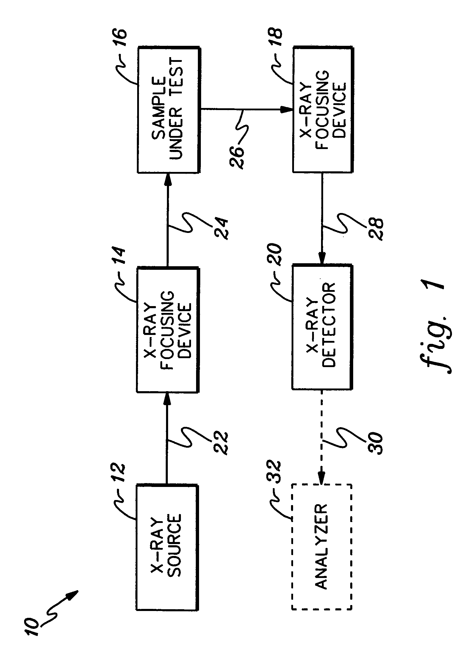
[0049]FIG. 1 illustrates a schematic block diagram of a typical system 10 used for exposing a substance to x-ray radiation to produce flourescent radiation which can then be detected and analyzed to determine a characteristic of the substance. Such a system typically includes an x-ray source 12, a first x-ray focusing device 14, a sample excitation chamber 16, a second x-ray focusing device 18, and an x-ray detector 20. The x-ray source 12, for example, an x-ray tube, produces a beam of x-rays 22. Since x-ray beam 22 is typically a divergent beam, beam 22 is diffracted or focused by means of one or more x-ray focusing devices 14. X-ray focusing device 14 may be one or more doubly-curved crystals, for example, a doubly-curved crystal having essentially parallel atomic planes, such as the crystals disclosed in pending application Ser. No. 09 / 667,966 filed on Sep. 22, 2000, the disclosure of which is incorporated by reference herein. X-ray focusing device may be one or more capillary-t...


PUM

PropertyMeasurementUnit
electric potentialaaaaaaaaaa
areaaaaaaaaaaa
areaaaaaaaaaaa

Abstract

A method and device for cooling and electrically-insulating a high-voltage, heat-generating component, for example, an x-ray tube (1105) for analyzing fluids by means of x-ray fluorescence. The device includes an x-ray source (1100) including an x-ray tube (1105) having improved heat-dissipating properties due to the thermal coupling of the x-ray tube with a thermally-conductive, dielectric material (1150). The device may include a base assembly (1135) mounted to the component for conducting heat away from the component while electrically isolating the component. In one aspect of the invention, the base assembly includes two copper plates (1140, 1145) separated by a dielectric plate (1150). The dielectric plate minimizes or prevents the leakage of current through the base assembly (1135). One aspect of the disclosed invention is most amenable to the analysis of sulfur in petroleum-based fuels.

Description

CROSS-REFERENCE TO RELATED APPLICATIONS[0001]This application is a continuation of PCT Application PCT / US2002 / 038803, filed Dec. 4, 2002, and published under PCT Article 21(2) in English as WO 2003 / 049138 A3 on Jun. 12, 2003, and is a continuation of U.S. Ser. No. 10 / 206,531 filed Jul. 26, 2002. PCT / US2002 / 038803 claimed the priority of the United States applications identified below, which are assigned to the same assignee as this application. The entire disclosures of PCT / US2002 / 038803 and the below-listed applications are hereby incorporated herein by reference in their entirety:[0002]“X-RAY TUBE AND METHOD AND APPARATUS FOR ANALYZING FLUID STREAMS USING X-RAYS” by Radley, et al. U.S. Ser. No. 60 / 336,584 filed Dec. 4, 2001;[0003]“A METHOD AND APPARATUS FOR DIRECTING X-RAYS” by Radley, U.S. Ser. No. 60 / 383,990 filed May 29, 2002;[0004]“X-RAY SOURCE ASSEMBLY HAVING ENHANCED OUTPUT STABILITY” by Radley, et al., U.S. Ser. No. 60 / 398,965 filed Jul. 26, 2002;[0005]“METHOD AND DEVICE FO...

Claims


Application Information

Patent Timeline
Patent Type & Authority Patents(United States)
IPC IPC(8): H01J35/10G01N23/12G01N23/223G21K1/00G21K1/02G21K5/02G21K5/08H01B7/00H01J35/12H01R4/00H05G1/00H05G1/04
CPCG01N23/12G01N23/223G21K1/06G01N2223/076Y10S439/936
Inventor RADLEY, IANBIEVENUE, THOMAS J.BURDETT, JR., JOHN H.GALLAGHER, BRIAN W.SHAKSHOBER, STUART M.CHEN, ZEWU
Owner S RAY OPTICAL SYST
Why Eureka
Try Eureka