

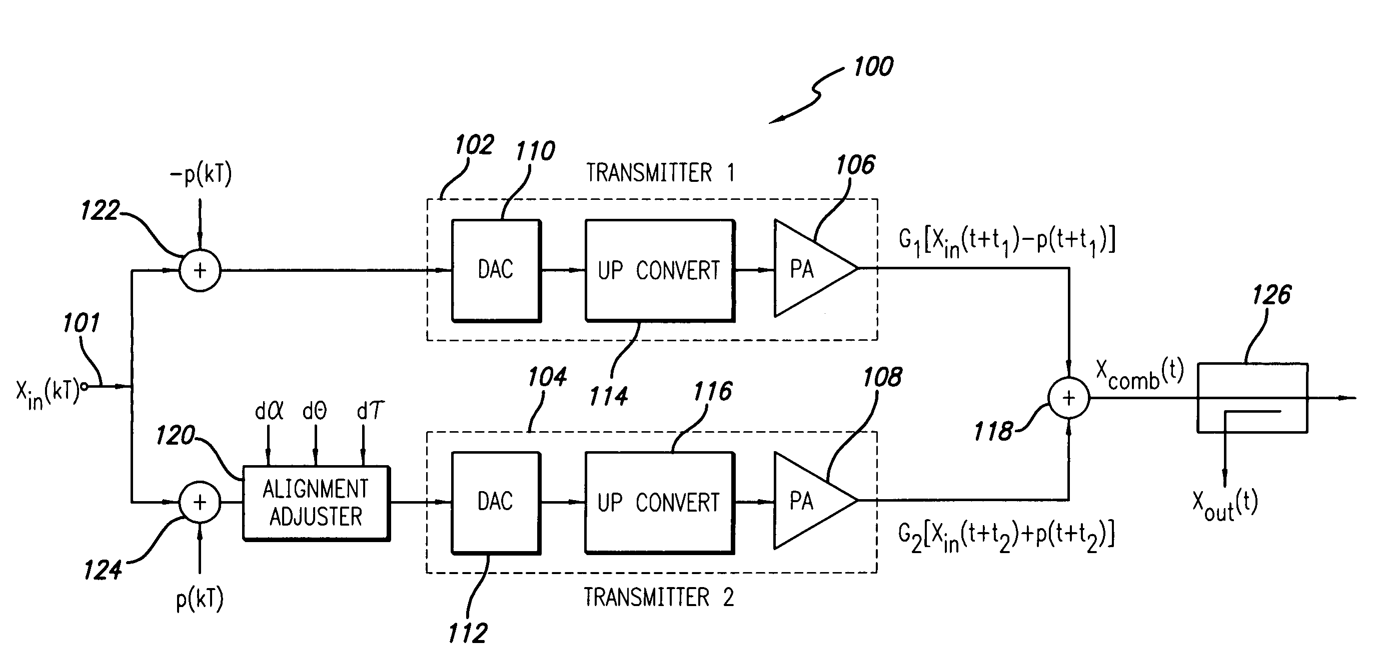
Multi-transmitter communication system employing anti-phase pilot signals
a multi-transmitter and pilot signal technology, applied in the field of wireless communication systems and methods, can solve the problems of destructive signal combination, misalignment of output combiners, and difficulty in maintaining such multi-transmitter systems perfectly aligned, and achieve the effect of minimizing the detected pilot signal
- Summary
- Abstract
- Description
- Claims
- Application Information
AI Technical Summary
Benefits of technology
Problems solved by technology
Method used
Image

Examples
first embodiment
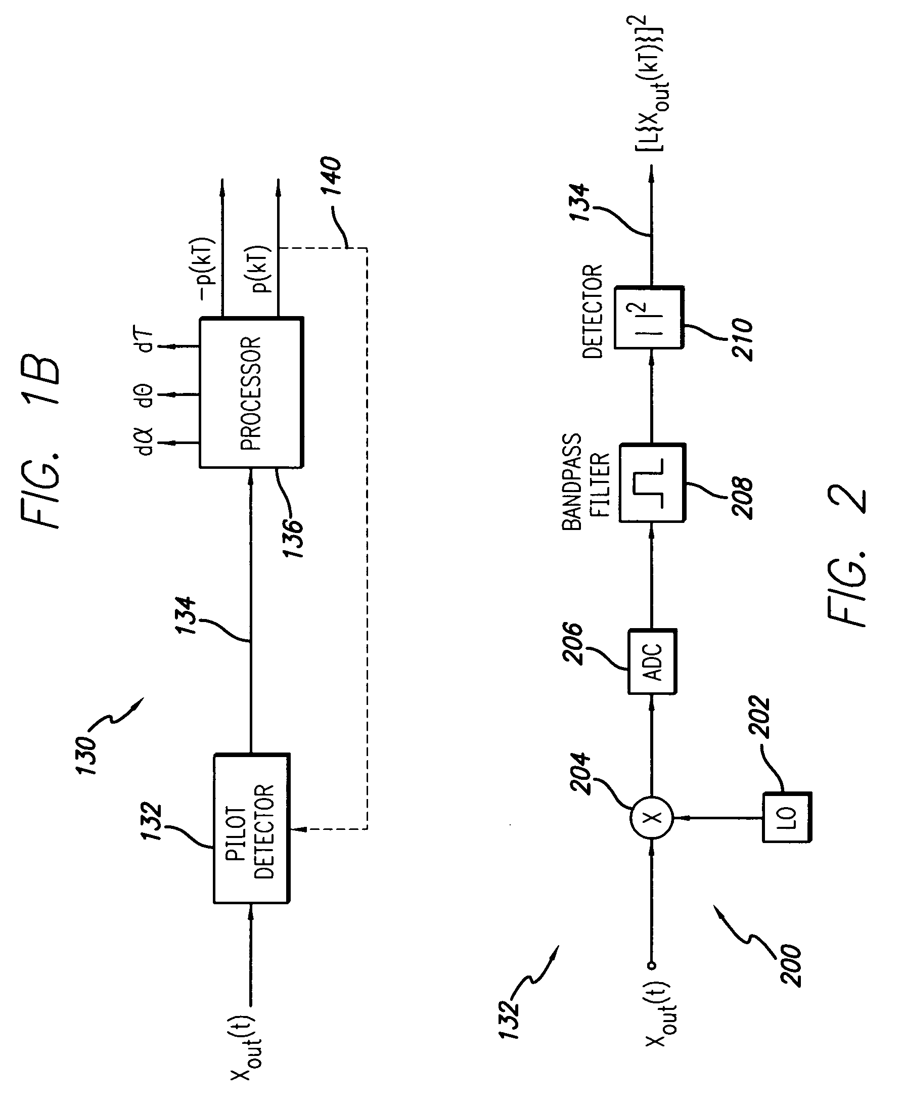
[0031]In the pilot detector 132, shown in FIG. 2, narrow bandwidth power detection uses filtering to isolate the pilot from the sampled RF signal, xout(kT). As shown, the output sampled signal is first down-converted to a lower frequency using a down converter 200, comprising local oscillator (LO) 202 and mixer 204. The down converted signal is then converted into a digital (sampled) format by an analog to digital converter (ADC) 206. Then digital signal processing is applied to filter and power detect the pilot signal. This processing may be provided by bandpass filter 208 and power detector 210, which may be discrete circuits or this processing may be implemented in a DSP (digital signal processor). The detected pilot power is:
Ppilot(kT)=Σ|L{xout(kT)}|2 (Eq. 9)
where xout(kT) is an output sample that has been down-converted and digitized and L{ } is a linear filtering operation that notches the input signal. That is,
Σ|L{xin(kT)}|2≈0 (Eq. 10)
and
Σ|L{p(kT)}|2>0 (Eq. 11)
[0032]The pi...
second embodiment
[0034]There are many variations of the two embodiments of the pilot detector described in relation to FIGS. 2 and 3 as will be apparent to those skilled in the art. For example, filtering and detection can be performed on the RF signal directly, eliminating the down conversion within the
third embodiment
[0035]In pilot detector 132, a correlation method may be employed. The correlation method is:
Cn=ΣLn{xout(kT)}·Ln{p*(kT+τ)}dt (Eq. 12)
where τ is the nominal time delay between the pilot injection and the output sample and Ln{ } represents a linear operation. The nominal time delay between the input signal and the output sample maximizes
[0036]An(τ)=∑kxout(kT)·xin*(kT+τ)dt.(Eq.13)
[0037]The linear operations used in (Eq. 12) may include bandpass filtering to allow the narrow bandwidth approximation to be used (see (Eq. 8)). The pilot and linear operations are selected such that
ΣLn{xin(kT)}·Ln{p*(kT)}dt≈0 (Eq. 14)
and
ΣLn{p(kT)}·Ln{p*(kT)}dt>0 (Eq. 15)
for each n. In general, several correlations Cn are computed using different filters in order to obtain sufficient information to estimate the gradient direction in the minimization process.
[0038]One method of implementing a set of narrow bandwidth filters is to use a Digital Fourier Transform (DFT), preferably a Fast Fourier T...
PUM
 Abstract
Description
Claims
Application Information