Washer nozzle and washer apparatus

a technology of washer nozzle and washer, which is applied in the direction of lighting and heating apparatus, vehicle cleaning, combustion types, etc., can solve the problems of uneven distribution of washer fluid quantity, small particle size of jetted washer fluid, and inability to quickly spread washer fluid, etc., to achieve quick and stable secure

Inactive Publication Date: 2006-09-26
DENSO CORP
View PDF18 Cites 16 Cited by
  • Summary
  • Abstract
  • Description
  • Claims
  • Application Information

AI Technical Summary

Benefits of technology

[0022]With using this washer apparatus, the drawbacks of conventional spread-type jet nozzles can be removed by the washer nozzle. Further, areas which sometimes remain unwashed by a wiper apparatus can be sprayed and supplied with washer fluid. Thus, wide fields of view for the driver and front-seat passenger can be quickly and stably secured.

Problems solved by technology

However, if the washer fluid is spread and jetted over a large area using such a spread-type jet nozzle, the distribution of the quantity of the jetted washer fluid is not uniform.
Therefore, the washer fluid is not quickly spread and some areas can be remained unwashed, especially, when muddy water is sticking to the windshield glass.
Further, in such a spread-type jet nozzle, the particle size of jetted washer fluid is relatively small.
Therefore, the jetted washer fluid is easily affected by the airflow when the vehicle is driving at high speed, and a splashdown of the washer fluid falls down from a target point.
As a result, the washer fluid is not supplied to the upper part of a windshield glass and a large unwashed area remains.
Accordingly, it is difficult to secure a sufficient field of view at the driver's side.
As a result, the jetted fluid is not effectively utilized.

Method used


Image

  • Washer nozzle and washer apparatus
  • Washer nozzle and washer apparatus
  • Washer nozzle and washer apparatus

Examples


first embodiment

[0046](First Embodiment)

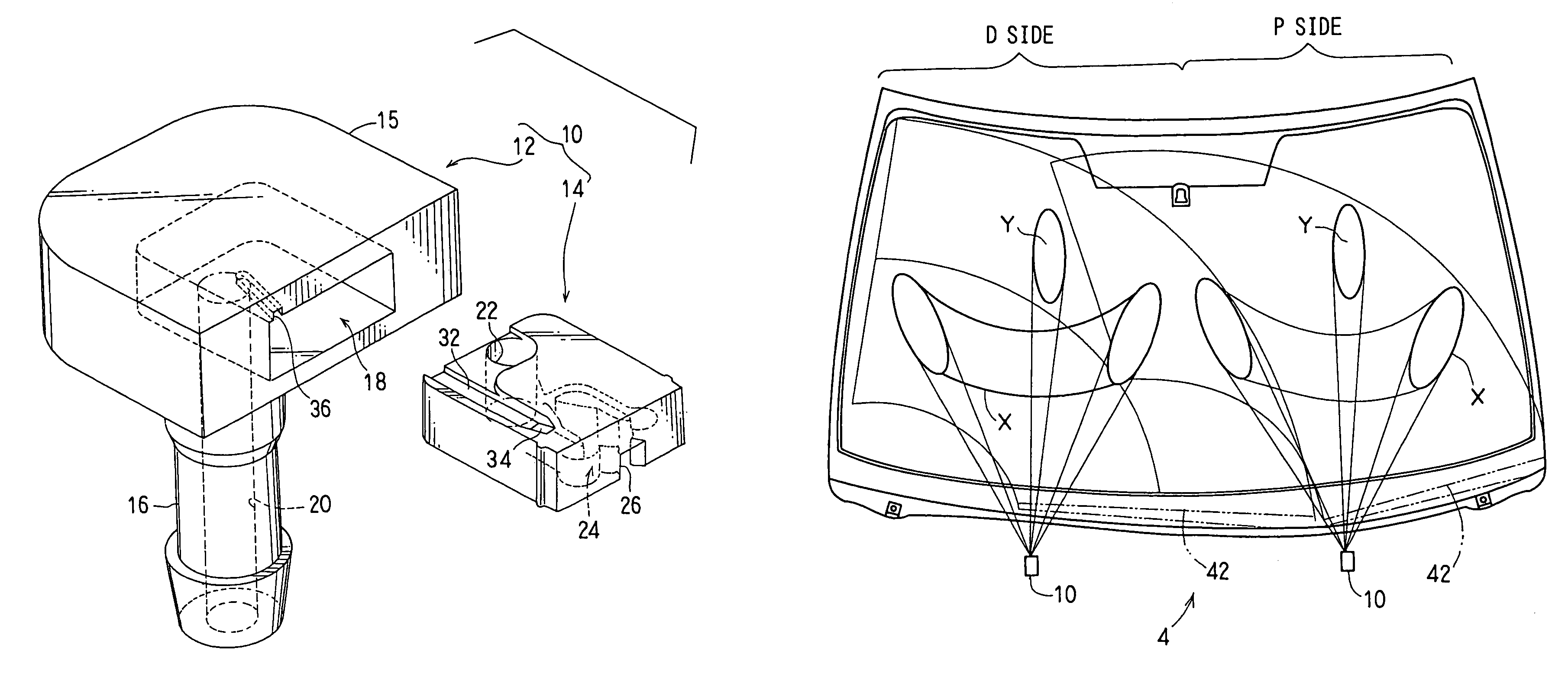
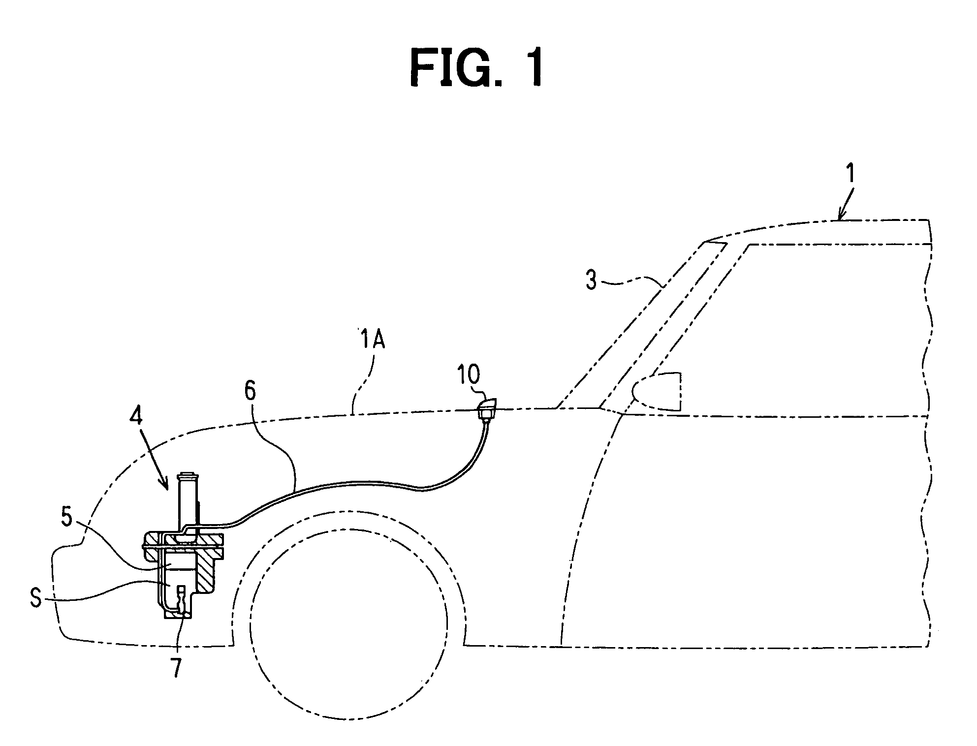
[0047]As illustrated in FIG. 1, a pair of left and right washer nozzles 10 is attached to a hood 1A of an automobile vehicle 1. (Only one washer nozzle 10 is illustrated in FIG. 1.) The washer nozzles 10 are disposed to direct to the left and right halves of a windshield glass 3, respectively. The washer nozzles 10 are parts of a washer apparatus 4 for vehicle installed at the front part of the vehicle. The washer apparatus 4 for vehicle includes a washer tank 5 for reserving washer fluid S; and a washer pump 7 for introducing the washer fluid S from the washer tank 5 to the washer nozzles 10 through a hose 6 under predetermined pressure.

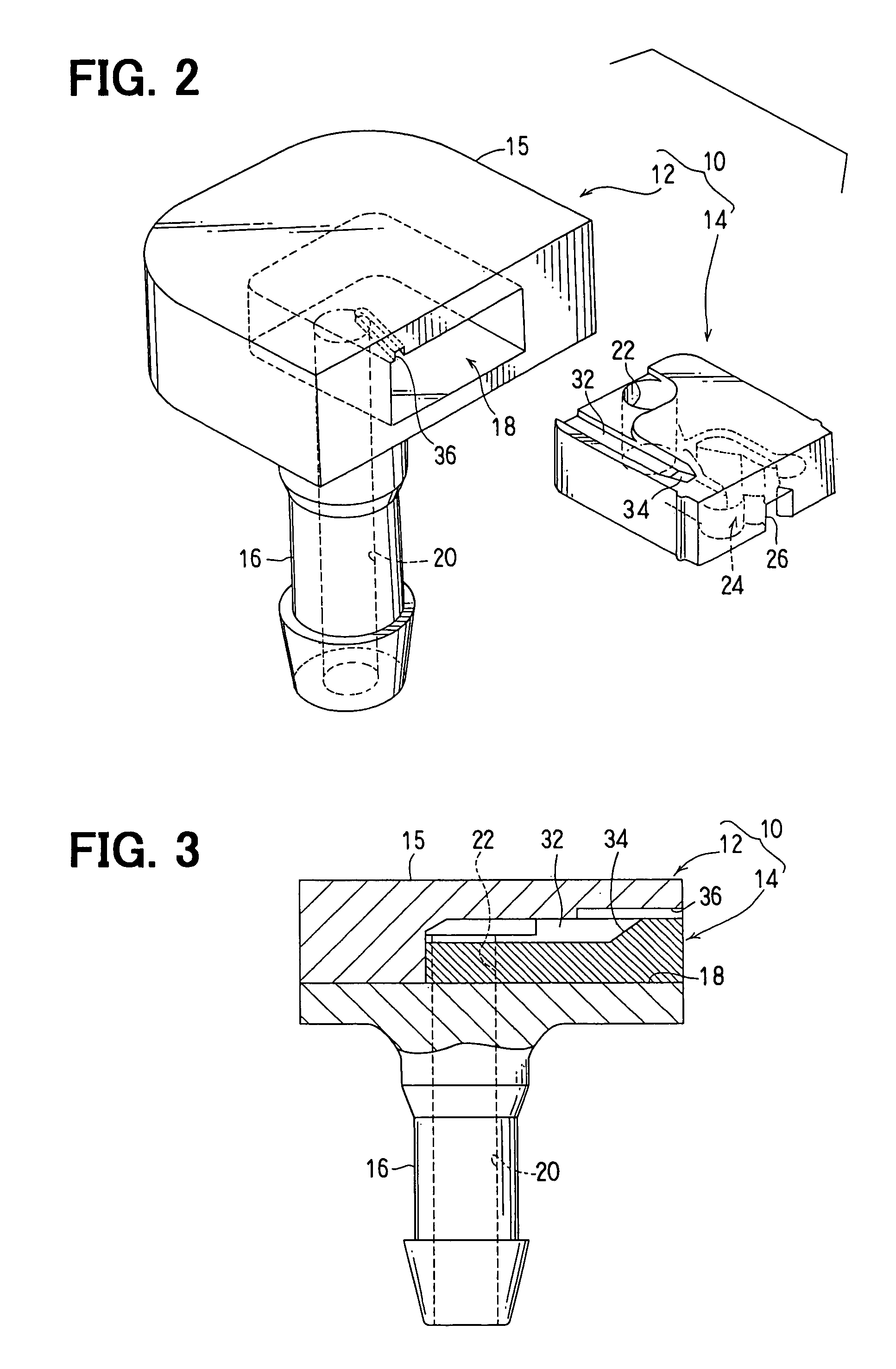
[0048]As illustrated in FIGS. 2 to 5, the washer nozzle 10 has a nozzle body 12 and a nozzle chip 14.

[0049]The nozzle body 12 is made of resin, and is mounted on the hood 1A of the vehicle with a head 15 thereof exposed. A cylindrical hose coupling portion 16 is formed at the lower end of the nozzle body 12, and the hose 6 co...

second embodiment

[0070](Second Embodiment)

[0071]As illustrated in FIG. 11, the washer nozzle 50 according to the second embodiment includes a nozzle body 52 and a nozzle chip 54.

[0072]A pair of locking hooks 53, which extends toward a head 52B, are formed on the side wall of a base 52A of the nozzle body 52. The nozzle body 52 is locked on the hood of the vehicle (not shown) with the head 52B thereof exposed.

[0073]As illustrated in FIG. 12 and FIG. 13, the nozzle chip 54 has the oscillation chamber 24 and the spread jet opening 26 formed on the underside thereof (that is disposed on the lower part of FIG. 12). This is the same as the nozzle chip 14 of the washer nozzle 10 in the first embodiment.

[0074]Further, a branch channel 56 and a jet opening 58 are formed on the underside of the nozzle chip 54. This branch channel 56 connects to the channel 22 (i.e., to the feed passage 20). Further, the branch channel 56 is formed continuously, linearly and integrally along with the main channel 28 in the osc...

third embodiment

[0078](Third Embodiment)

[0079]In the first and second embodiments, the jet flow from the jet opening 36 compensates to the insufficient fluid areas where the distribution of the quantity of fluid is sparse with respect to the spray pattern of the spread flow from, for example, the spread jet opening 26. In this embodiment, the jet flow from the jet opening 36 is not used only for the purpose of complementarily supplying washer fluid. The jet is also used to check the coverage of spray of the spread flow from the spread jet opening 26. That is, in this embodiment, the jet can be also used as a checking jet for visually checking the coverage of spray of washer fluid S from the spread jet opening 26 with ease and accuracy.

[0080]As illustrated in FIG. 14, the washer nozzle 10 includes the nozzle body 12 and the nozzle chip 14 as a jetting element. The nozzle body 12 has a base 12A formed in substantially cylindrical shape and a head 12B, which extends from the upper end of the base 12A ...


PUM


Abstract

A washer nozzle includes a spread jet opening for basically jetting washer fluid in a predetermined direction of a vehicle; and a jet opening for accessorily and intensively jetting part of the washer fluid as a directional jet flow which is different from the spread flow basically jetted from the spread jet opening. The washer fluid is jetted and sprayed over a large area in a fan-shaped spread flow from the spread jet opening. Further, the washer fluid is intensively sprayed as the directional jet flow from the jet opening. Thus, sweeping performance of the washer nozzle and a washer apparatus is improved such that the directional jet flow is not substantially affected by airflow during high-speed driving so that the washer fluid is effectively utilized so as to be sprayed and supplied to areas that are prone to be left unwashed.

Description

FIELD OF THE INVENTION[0001]The present invention relates to a washer nozzle and a washer apparatus for jetting washer fluid pumped under pressure to wash windshield glass or the like of, for example, a vehicle.BACKGROUND OF THE INVENTION[0002]A washer apparatus suitably used for automobile is required to wipe a large area with a small quantity of washer fluid in a short time. On this account, spread (spray)-type jet nozzles which are capable of jetting washer fluid over a large area to increase wiped areas have been proposed (e.g. Japanese Unexamined Patent Application Publication No. 2002-67887).[0003]In this type of washer nozzle, a nozzle chip is built in a nozzle body and further the nozzle chip has an oscillation chamber for self-oscillating the pumped washer fluid. In the oscillation chamber, a channel of washer fluid fed through a feed passage in the nozzle body is formed (main channel). In addition, a plurality of feedback channel is formed therein for branching, guiding, a...

Claims


Application Information

Patent Timeline
Patent Type & Authority Patents(United States)
IPC IPC(8): B05B1/10A62C31/02B05B1/08B05B1/14B60S1/46B05B1/04B05B15/06B60S1/50B60S1/52
CPCB05B1/042B05B1/08B60S1/52B60S1/50B05B15/067B05B15/654B05B1/10
Inventor MARUYAMA, AKIRAKANAZAWA, KEISUKE
Owner DENSO CORP
Why Eureka
Try Eureka