Method and apparatus for machining a blank from all directions

a technology of machining and blanks, applied in mechanical equipment, turbines, manufacturing tools, etc., can solve the problems of damage to workpieces and inadequate quality of final workpieces, and achieve the effect of reducing the moments occurring during such machining and preventing possible vibrations

Inactive Publication Date: 2006-09-26
GENERAL ELECTRIC TECH GMBH
View PDF32 Cites 11 Cited by
  • Summary
  • Abstract
  • Description
  • Claims
  • Application Information

AI Technical Summary

Benefits of technology

[0009]The reduction in setups leads to a considerable simplification in the production process and to cost savings (less downtime, fewer means for the transfer of components, etc.) and nonetheless permits the production of final shapes which meet the highest quality requirements.
[0011]According to a first preferred embodiment of the invention, the blank is a blank made of metal or a ceramic material in the form of a cylindrical or polyhedral, in particular preferably parallelepiped-shaped, block or is a cast blank or forged blank. It is likewise possible to feed the blank to the method according to the invention in an already pre-machined form. Surprisingly, the method according to the invention is also successful with such difficult-to-machine components, and this without loss of quality of the final shaped parts.
[0012]According to a further preferred embodiment of the invention, the partly machined blank is cleaned and / or measured after the first machining step, for which purpose it is in particular preferably removed in a defined mounting from the machining region of the machine tool or milling machine and cleaned and / or measured in a measuring station. This step between the two actual machining steps permits, on the one hand, final quality control of the already machined region of the workpiece, this in an especially simple manner if the partly machined workpiece is removed in a defined manner from the machining space of the machine tool or milling machine. In this context, “defined manner” means that the means for removing the partly machined workpiece grip the latter at a well-defined location, so that the partly machined workpiece can then be fixed and measured in a likewise well-defined position in a measuring station. This is in particular possible in a very effective manner if, for the defined mounting during the first machining step, defined (temporary) gripping surfaces are prepared in the remaining regions, i.e. in those regions which have not yet been machined into an actual functional surface in the first machining step, via which gripping surfaces transport means, in particular in the form of grippers, and / or mounting means of the measuring station or of a cleaning unit, respectively, in particular in the form of grippers, can mount the partly machined blank in a defined position.
[0015]A particular embodiment of the method according to the invention works in such a way that the blank is first of all shaped on its one side in the first machining step and is then shaped on its other side in the second machining step. That is to say the first adapter grips the blank at a first end, in the first machining step the second end of the blank is given its final partial shape corresponding to the intended use, the second adapter then grips the partly machined blank at the partial shape and, in the second machining step, the first end is processed into the final overall shape. If the final overall shape involves a turbine blade, the root region is preferably processed in the first machining step, then this root region is used for the mounting for the second machining step, and the tip region is processed in the second machining step. The opposite process can also be realized, in particular in the case of a turbine blade with a shroud band; that is to say that the tip region with shroud band is processed in the first step. In addition, it proves to be advantageous, in this case, in the first machining step, for two defined gripping surfaces in the form of blind holes or recesses to be milled on each of two opposite sides of the blank (of course in such a way that the functional surfaces to be subsequently provided in the second machining step are not affected by these recesses), a first (top) pair being used for the gripping with the gripper for removing the partly machined blank from the machining region of the machine tool or milling machine and for reinserting said partly machined blank, and a second (bottom) pair being used for the defined fixing of the partly machined blank on the measuring station. In this case, if appropriate, in the second machining step, a center hole can be milled on the side remote from the root, and a traversable and / or pivotally mounted tailstock for the mounting can be moved into this center hole at least during some stock removal steps during the second machining step. It can thus be ensured that the moments occurring during such machining can be reduced or that possible vibrations can be prevented.

Problems solved by technology

Normally, it has always been assumed that the forces produced during the machining lead either to damage to the workpiece or to inadequate quality of the final workpiece (e.g. as a result of vibrations, moments, etc.).

Method used


Image

  • Method and apparatus for machining a blank from all directions
  • Method and apparatus for machining a blank from all directions
  • Method and apparatus for machining a blank from all directions

Examples


Embodiment Construction

[0047]First of all, possible layouts of cells for the machining according to the invention of workpieces are to be shown and explained with reference to FIGS. 1 to 3, then the actual process sequences of the two essential exemplary embodiments are to be shown and explained with reference to FIGS. 4 and 5.

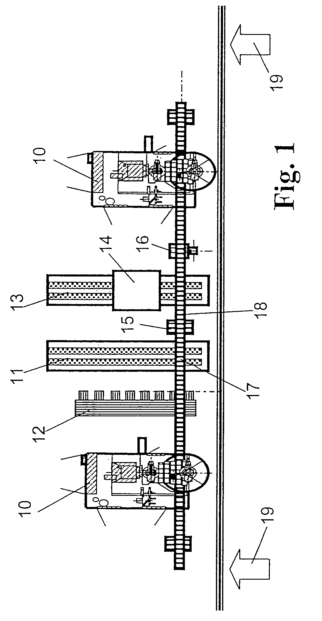
[0048]FIG. 1 shows the layout of a cell from above for carrying out the process according to the invention. This is a small cell having two blade milling machines 10 which are loaded with the workpieces to be machined and are respectively unloaded via a handling portal 18. To this end, the handling portal 18 has a handling system with a gripper 16. If appropriate, a plurality of such handling systems 16 can be mounted on the same handling portal 18 in a traversable manner. The handling portal 18, via further units essentially remote from a working front 19, is supplied with blanks by means of a loading belt 11 in the form of a paternoster. The blanks are gripped by the gripper of th...


PUM

PropertyMeasurementUnit
weightaaaaaaaaaa
diameteraaaaaaaaaa
lengthaaaaaaaaaa

Abstract

In a method of machining a blank from all directions using at least one machine tool, such as a milling machine, production of the ready-to-use, measured component which is controlled and classified with regard to quality, such as a turbine blade, occurs in as few steps and setups as possible with the use of machine tools and milling machines that as far as possible are of identical design. The blank, in a first machining step, is held by at least one first adapter and a first region is given its final partial shape corresponding to the intended use by a machine tool or milling machine. In a second machining step, the partly machined blank is held by at least one second adapter in the first, finally machined region, and the remaining region is given its final overall shape corresponding to the intended use by a machine tool or milling machine.

Description

CROSS-REFERENCE TO RELATED APPLICATIONS[0001]This application is a continuation of the U.S. National Stage designation of co-pending International Patent Application PCT / CH03 / 00052 filed Jan. 23, 2003, the entire content of which is expressly incorporated herein by reference thereto.FIELD OF THE INVENTION[0002]The present invention relates to a method of machining blanks or pre-machined workpieces from all directions using at least one machine tool, such as a milling machine for example, in order to produce ready-to-deliver components which are finally machined in their three-dimensional shape.BACKGROUND OF THE INVENTION[0003]During the production of turbine blades, work is normally carried out with multi-spindle machining. This means that a blank is first of all subjected to rough pre-machining, then the airfoil region is processed in detail, and then the tip and finally the root are produced. Between these individual machining steps, the workpiece must be reset in each case by han...

Claims


Application Information

Patent Timeline
Patent Type & Authority Patents(United States)
IPC IPC(8): B23C3/16B23Q11/00B23C3/00B23C3/18B23Q3/06B23Q7/04B23Q39/04
CPCB23C3/18B23Q7/047B23Q39/048B23B2215/81B23C2215/44B23Q2230/008Y10T29/49316Y10T409/303136Y10T409/309016Y10T409/303808Y10T409/307448Y10T29/49336Y10T409/303864Y10T29/49996
Inventor KILLER, FRANZSCHERER, JOSEF
Owner GENERAL ELECTRIC TECH GMBH
Why Eureka
Try Eureka