Plasticizing unit with an electromotive spindle drive for an injection molding machine

a technology of electromotive spindle drive and plasticizing unit, which is applied in the field of actuating drive of an injection molding machine, can solve the problems of significantly reducing the relief provided by the energy storage device, negatively affecting the total energy consumption of the drive unit, and reducing the power required by the electromotive spindle drive only in a limited way, so as to achieve the effect of boosting the power of the electric motor

Inactive Publication Date: 2006-09-26
SUMITOMO SHI DEMAG PLASTICS MACHINERY
View PDF13 Cites 6 Cited by
  • Summary
  • Abstract
  • Description
  • Claims
  • Application Information

AI Technical Summary

Benefits of technology

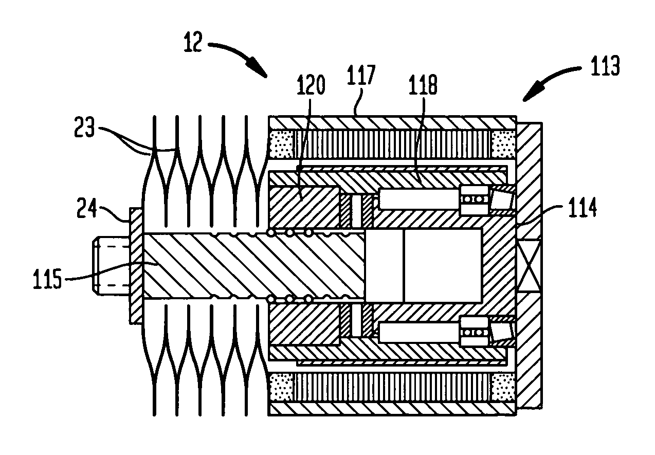
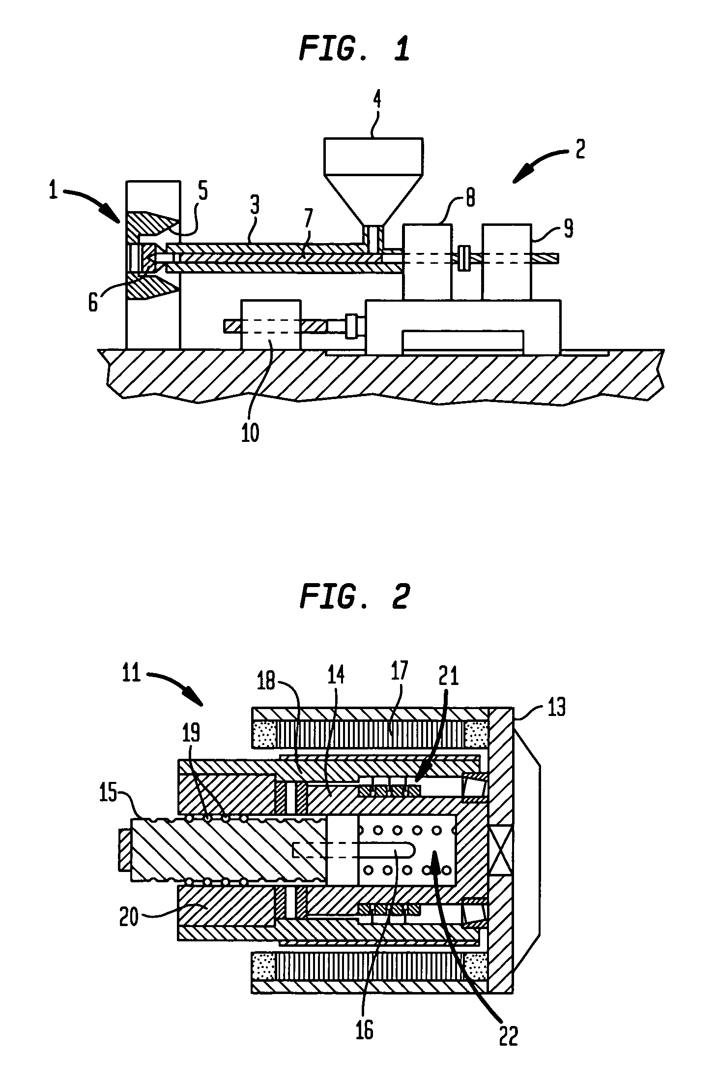
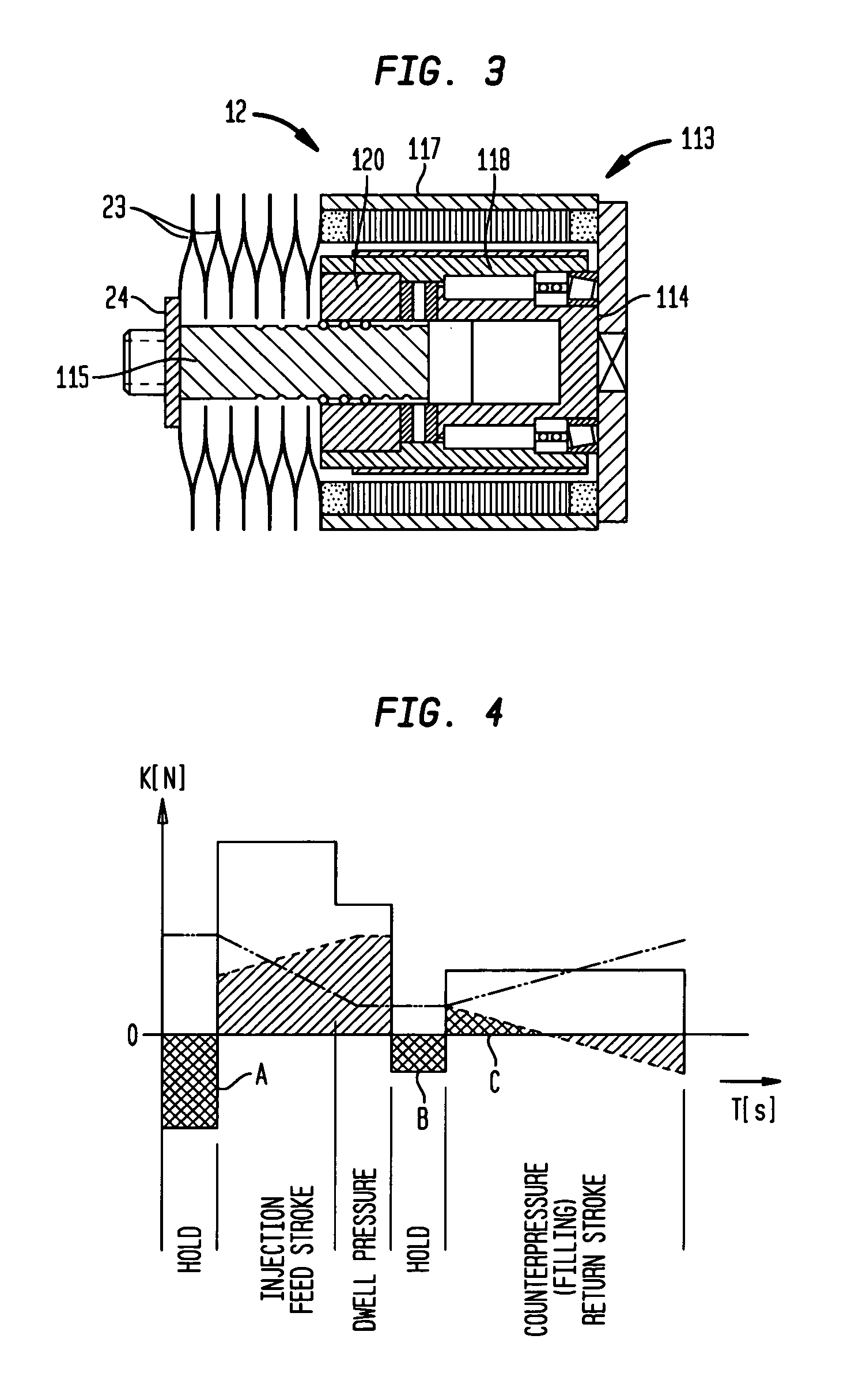
[0006]According to one aspect of the present invention, an actuating drive for a plasticizing unit of an injection molding machine includes a spindle drive with a stationary housing section and an electric motor with a drive element. The spindle drive further includes a control mechanism arranged between the drive element and the housing section, and an energy storage device coupled with the spindle drive for force transmission therebetween. The spindle drive loads the energy storage device in a return stroke phase of the spindle drive and unloads the energy storage device in a feed phase of the spindle drive, whereby unloading of the energy storage device boost the power of the electric motor. The control mechanism operates in parallel with the energy storage device to actively modify an effective actuating force of the energy storage device dependent on a stroke position of the spindle drive.
[0007]The energy storage device is a mechanical device which essentially stores kinetic energy. According to the invention, the effective actuating force of the energy storage device is intentionally adjusted by a simple control mechanism so that the spindle drive can be held stationary in an arbitrary stroke position, in particular in the forward (feed) or return stroke in position, by the electric motor without consuming energy. Alternatively or in addition, an adjustable positive or negative force difference, depending on the stroke direction, can be produced—again without activating the electric motor—between the spring force of the energy storage device. The spring force is defined by the spring constants and the effective actuating force exerted by the energy storage device in conjunction with the control mechanism. The spindle drive meets the overall variable speed and force requirements of an actuating drive for the plasticizing unit of an injection molding machine without adding significant construction and energy costs.

Problems solved by technology

However, the relief provided by the energy storage device is significantly reduced in that the characteristic spring curve of the energy storage device does not conform to the force and speed requirements of a plasticizing drive which can vary significantly depending on the stroke and can therefore negatively effect the total energy consumption of the drive unit.
As a result, the compression spring assembly reduces the power required by the electromotive spindle drive only in a limited way.

Method used


Image

  • Plasticizing unit with an electromotive spindle drive for an injection molding machine
  • Plasticizing unit with an electromotive spindle drive for an injection molding machine
  • Plasticizing unit with an electromotive spindle drive for an injection molding machine

Examples


Embodiment Construction

[0018]Throughout all the Figures, same or corresponding elements are generally indicated by same reference numerals. These depicted embodiments are to be understood as illustrative of the invention and not as limiting in any way. It should also be understood that the drawings are not necessarily to scale and that the embodiments are sometimes illustrated by graphic symbols, phantom lines, diagrammatic representations and fragmentary views. In certain instances, details which are not necessary for an understanding of the present invention or which render other details difficult to perceive may have been omitted.

[0019]This is one of two applications both filed on the same day. Both applications deal with related inventions. They are commonly owned but have different inventive entity. Both applications are unique, but incorporate the other by reference. Accordingly, the following U.S. patent application with Ser. No. 10 / 689,555 is hereby expressly incorporated by reference: “Injection ...


PUM

PropertyMeasurementUnit
energyaaaaaaaaaa
transferred energy boosting poweraaaaaaaaaa
forceaaaaaaaaaa

Abstract

An actuating drive for a plasticizing unit of an injection molding machine is disclosed. The actuating drive includes a spindle drive with an electric motor and a control mechanism. An energy storage device is coupled with the spindle drive for force transmission therebetween. The energy storage device is loaded by the spindle drive in a return stroke phase and is unloaded in a forward feed phase, boosting the power of an electric motor. The actuator drive can be used, for example, for pulsating actuation of a mold ejector of the injection molding machine, significantly reducing the electrical energy consumption compared to conventional drives.

Description

CROSS-REFERENCES TO RELATED APPLICATIONS[0001]This application is a continuation of prior filed copending PCT International application no. PCT / EP02 / 04231, filed Apr. 17, 2002, on which priority is claimed under 35 U.S.C. §120, the disclosure of which is hereby incorporated by reference.[0002]This application claims the priority of Austrian Patent Application, Serial No. A 632 / 01, filed Apr. 19, 2001, pursuant to 35 U.S.C. 119(a)-(d), the disclosure of which is incorporated herein by reference.BACKGROUND OF THE INVENTION[0003]The present invention relates to an actuating drive for a plasticizing unit of an injection molding machine, and more particularly to an actuating drive with a spindle drive for pulsating actuation of a mold ejector to reduce the electrical energy consumption of the spindle drive.[0004]International patent publication WO 97 / 34757 describes a spindle drive operating as an actuating drive for an injection molding machine. The actuating drive includes an electric ...

Claims


Application Information

Patent Timeline
Patent Type & Authority Patents(United States)
IPC IPC(8): B29C45/50B29C45/40
CPCB29C45/4005B29C45/5008B29C2045/1798
Inventor ICKINGER, GEORG MICHAEL
Owner SUMITOMO SHI DEMAG PLASTICS MACHINERY
Why Eureka
Try Eureka