Rack enclosure

a technology for enclosures and equipment, applied in the field of enclosures, can solve the problems of unreliable performance, equipment racks and enclosures generally cannot provide adequate cooling and ventilation, and equipment air intakes using side-to-side airflow often do not receive the cooling air required for proper operation of equipment, etc., to achieve easy and rapid reconfiguration, simplify the planning, design and maintenance of a data center or network room, and enhance the security and protection of equipmen

Active Publication Date: 2006-09-26
AMERICA POWER CONVERSION CORP
View PDF11 Cites 266 Cited by
  • Summary
  • Abstract
  • Description
  • Claims
  • Application Information

AI Technical Summary

Benefits of technology

[0007]In general, in an aspect, the invention provides an improved enclosure means for electronic equipment that accommodates cooling and ventilating requirements of different types of equipment. In one aspect, the invention provides an enclosure means configured to separate cooling intake air from exhaust air vented by equipment during operation to facilitate sufficient cooling and to prevent overheating of the equipment. In another aspect, the invention provides an enclosure means configured to separate cooling intake air from exhaust air vented by equipment using side-to-side airflow for cooling and ventilating. Another aspect of the invention provides an enclosure configured to simultaneously accommodate different cooling requirements of different types of rack-mounted equipment using front-to-back airflow or side-to-side airflow within the same enclosure, while separating cooling intake air from exhaust air. A further aspect of the invention provides an enclosure having an interior defining a plenum or chamber constructed and arranged to receive and to contain cooling air for intake by equipment using side-to-side airflow for cooling. In another aspect, a chamber or plenum can be configured within an equipment enclosure wherein the chamber or plenum is constructed and arranged to contain cooling air for intake by equipment using side-to-side airflow and to prevent air loss from the chamber or plenum. Yet another aspect of the invention provides an enclosure having an adaptable configuration to meet different airflow requirements of equipment using front-to-back airflow and equipment using side-by-side airflow for cooling and ventilating. Still a further aspect of the invention provides a system of barriers, partitions, interconnections and other components to permit an interior of an enclosure, and / or an equipment rack housed within the enclosure, to be easily and rapidly configured and arranged for mounting different types of equipment and for simultaneously supporting different airflow patterns used by the equipment for cooling and ventilating.

Problems solved by technology

Advancements in information technology (IT) equipment present challenges in creating a more effective IT environment in data centers and networking facilities.
However, IT equipment racks and enclosures generally cannot provide adequate cooling and ventilation for equipment that typically uses a side-to-side airflow, such as certain types of telecommunications equipment.
As a result, the air intakes of equipment using side-to-side airflow often do not receive sufficient cooling air required for proper operation of the equipment.
Insufficient cooling air can cause overtemperature shutdown and unreliable performance and reduced lifetime of the equipment.
IT equipment enclosures and racks configured to provide front-to-back airflow, therefore, are essentially incompatible with airflow patterns of some types of electronic equipment using side-to-side airflow for cooling and ventilating, such as certain types of telecommunications components.
Open-frame configurations do not confine hot and warm exhaust air within an enclosure or around equipment air intakes; however, such configurations do not prevent circulation of exhaust air to equipment air intakes and, therefore, do not overcome problems of insufficient cooling and overheating of equipment.
Telecommunications equipment disposed in side-by-side rack configurations are susceptible to direct intake of exhaust air vented from adjacent or neighboring equipment and, as a result, have an increased risk of overheating during operation.
Such top-mounted fans, however, do not assure sufficient cooling air will be provided to air intakes of all equipments components mounted in a rack.
Nor do top-mounted fans prevent exhaust air from circulating to air intakes of such components.
Top-mounted fans can further overdrive airflow through a rack and can cause significant mixing of exhaust air with cooling air.
Mixing exhaust air with cooling air can reduce the efficiency of a network room or data center's cooling system.
Using top-mounted fans limits the space available on an enclosure top for other functions, including data and power cabling.
In addition, top-mounted fans restrict the size and location of equipment that can be mounted in upper sections of the enclosure due to interference with fan airflow.
Separation of exhaust air from cooling air is a result of proper installation of rack enclosures; however, present enclosure and rack designs and cooling solutions for electronic equipment using side-by-side airflow do not separate exhaust air from cooling air.
Current designs of telecommunications equipment, however, may consume 6 kW or more per rack, and, thus, require effective cooling methods.

Method used


Image

  • Rack enclosure
  • Rack enclosure
  • Rack enclosure

Examples


Embodiment Construction

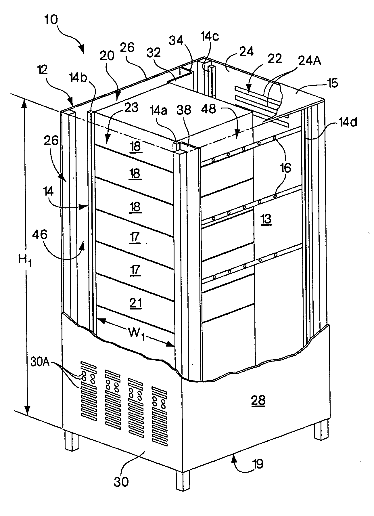
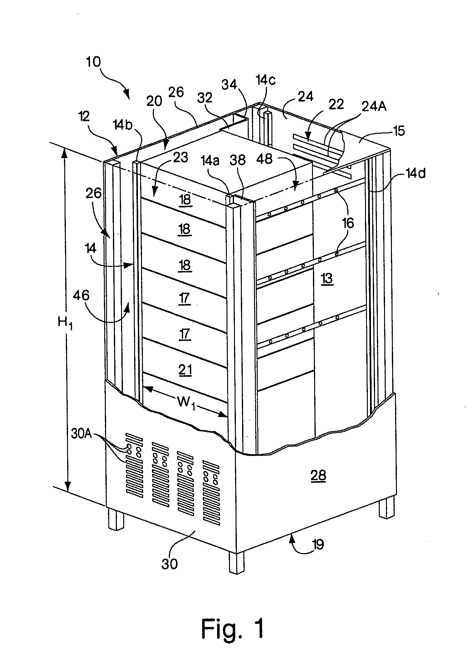
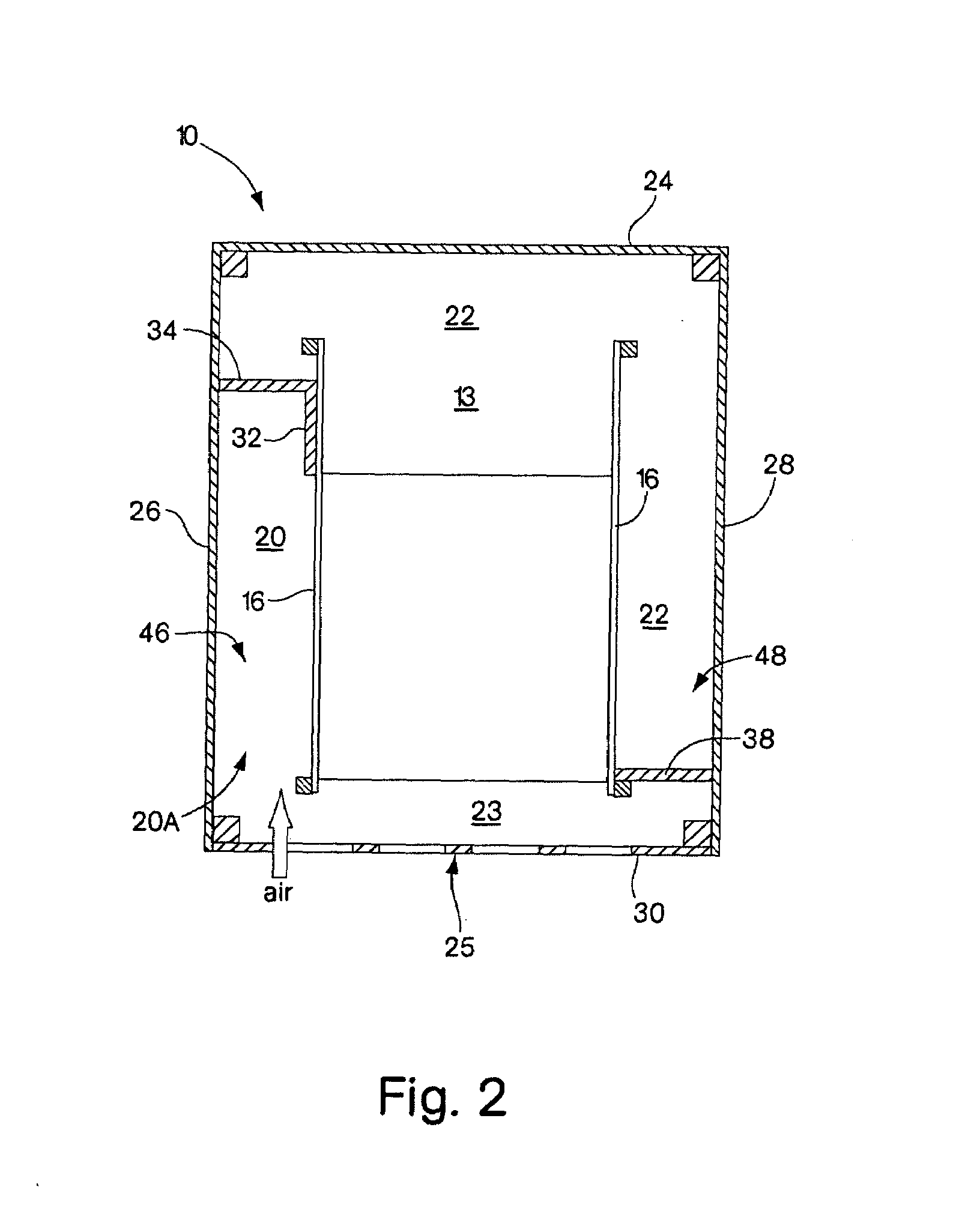
[0084]Aspects of the invention include an equipment rack enclosure having an interior configured for facilitating defined airflow conditions within the enclosure to meet cooling and ventilating requirements of rack-mounted equipment where the enclosure interior is structured and / or arranged to permit front-to-back airflow, e.g., used by information technology (IT) equipment, and side-to-side airflow, e.g., used by certain types of telecommunications equipment. An exemplary enclosure includes at least a first air intake plenum defined in the enclosure interior and disposed to contain cooling air that is directed and / or diverted from a front-to-back airflow to permit air to flow side-to-side through one or more sections of a rack. Different embodiments of an enclosure according to the invention permit an enclosure interior to be configured or adapted to accommodate different dimensions, e.g., depths, of different types of electronic equipment, while permitting airflow to meet the cool...


PUM


Abstract

An enclosure is provided for housing electronic equipment that accommodates the different cooling and ventilating requirements of different types of equipment. The enclosure is constructed and arranged to support cooling airflow in a front-to-back configuration through the enclosure and in a side-to-side configuration from one side to an opposite side of the enclosure. The enclosure can thereby provide within a single enclosure means cooling air for components using front-to-back airflow for cooling, such as information technology (IT) equipment, and for components using side-to-side airflow, such as certain types of telecommunications equipment. The enclosure can thereby support a mix of IT and telecommunications equipment, providing flexibility and adaptability in network room and data center configuration. The enclosure is further configured to separate intake air used by equipment for cooling from exhaust air vented by equipment into its interior during operation. As a result, the enclosure promotes sufficient equipment cooling and prevents / minimizes equipment overheating.

Description

PRIOR RELATED PATENT APPLICATIONS[0001]This application is a continuation-in-part patent application under 37 C.F.R. § 1.53(b) of U.S. nonprovisional patent application Ser. No. 10 / 436,886 filed on May 13, 2003, which is incorporated herein by reference.FIELD OF THE INVENTION[0002]The invention relates to an enclosure for use with rack-mounted equipment.BACKGROUND OF INVENTION[0003]Advancements in information technology (IT) equipment present challenges in creating a more effective IT environment in data centers and networking facilities. Equipment enclosures designed for high power density applications employing servers and networking equipment typically must provide not only effective cable management and power distribution, but also adequate cooling and ventilation to assure proper and reliable operation of equipment. Equipment rack enclosures for use in such high heat generating applications are primarily configured and equipped to provide front-to-back airflow to accommodate th...

Claims


Application Information

Patent Timeline
Patent Type & Authority Patents(United States)
IPC IPC(8): H05K5/06H01L23/46H01L23/467H05K7/20
CPCH05K7/20572H05K7/20736H01L2924/0002H01L2924/00
Inventor RASMUSSEN, NEILGERMAGIAN, MARK H.AVELAR, VICTOR P.DONOVAN, JAMES EDWARD
Owner AMERICA POWER CONVERSION CORP
Why Eureka
Try Eureka