Dynamic bioabsorbable fastener for use in wound closure

a bioabsorbable and dynamic technology, applied in the direction of surgical staples, prostheses, osteosynthesis devices, etc., can solve the problems of viscoelastic quality or polymer creep of thermoplastic polymers used in typical bioabsorbable staples, and achieve the effect of increasing the lateral pressure of the bioabsorbable fastener

Inactive Publication Date: 2006-09-26
INCISIVE SURGICAL
View PDF207 Cites 1545 Cited by
  • Summary
  • Abstract
  • Description
  • Claims
  • Application Information

AI Technical Summary

Benefits of technology

[0013]First, the thermoplastic polymers used in typical bioabsorbable staples possess a viscoelastic quality or polymer creep when subjected to continuous stress loading due to the nature of their molecular level bonding and entanglements. Traditionally, bioabsorbable fastener designs have compensated for this creep by either thickening the backspans or staple legs to prevent or reduce the deformation of the staple, or adding retaining clips or latches to preclude such deformation. Instead of trying to counteract the viscoelastic qualities of the polymer, the present invention takes advantage of these properties to provide for a dynamic response to lateral tissue forces that can deform the fastener, but not so far that the cleats of the fastener would release the tissue in the durable tissue retention zone.
[0015]Finally, when fastening opposing sides of a wound, the opposing sides must be physically approximated during placement of the fastener. Once the opposing sides have been retainably fastened, the opposing sides tend to return to a more relaxed disposition during the healing process, thereby increasing lateral pressure on the bioabsorbable fastener. In conventional practice, the bioabsorbable fastener ends up being over-designed in order to assist in the initial approximation of the tissue that can result in a design that is more susceptible to failure as a result of the longer term lateral pressures applied during the wound healing process. In contrast, the bioabsorbable fastener of the present invention is designed for use with an insertion apparatus that mechanically approximates the opposing sides of wound tissue to insure the creation of consistent and repeatable pierced openings into which the fastener is positioned in a through-and-through manner to take advantage of elastically securing the tissue within the durable issue retention zones created by the cleats of the fastener.

Problems solved by technology

First, the thermoplastic polymers used in typical bioabsorbable staples possess a viscoelastic quality or polymer creep when subjected to continuous stress loading due to the nature of their molecular level bonding and entanglements.

Method used


Image

  • Dynamic bioabsorbable fastener for use in wound closure
  • Dynamic bioabsorbable fastener for use in wound closure
  • Dynamic bioabsorbable fastener for use in wound closure

Examples


Embodiment Construction

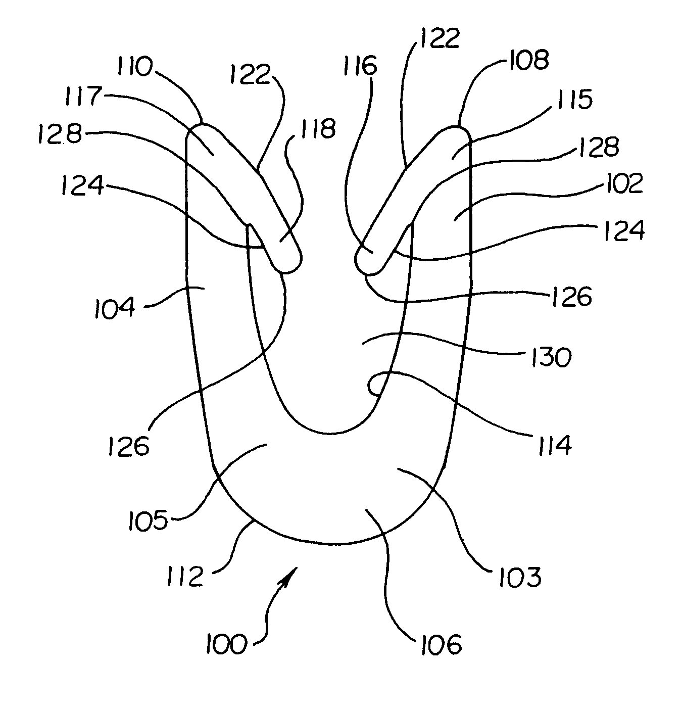
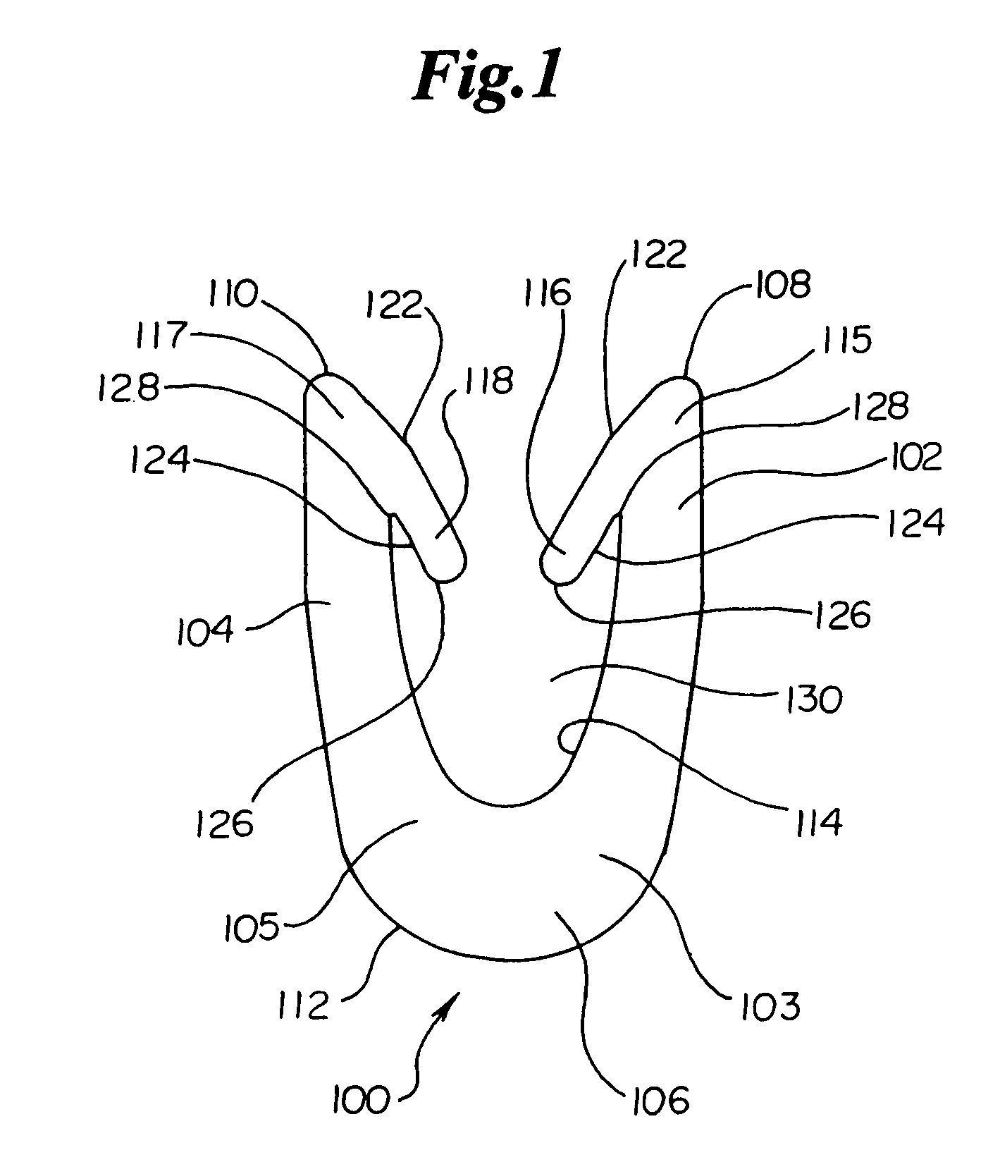
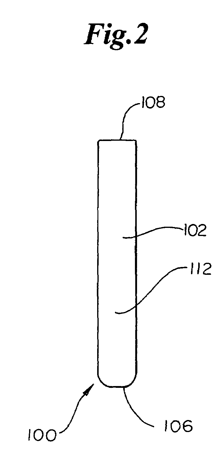
[0048]Depicted in FIGS. 1–3 is a preferred embodiment of a dynamic, bioabsorbable fastener 100 of the present invention. Generally, fastener 100 comprises a pair of arms102, 104 being operably connected with a common backspan 106 at shoulder portions 103 and 105, also depicted in FIG. 5, respectively. Arms 102, 104 each preferably include a rounded tip 108, 110. Fastener 100 is further defined by an arcuate exterior, perimeter surface 112 and an arcuate interior surface 114. The arcuate shape of interior surface 114 functions to even out and focus staple loading forces and reduces potential rocking of fastener 100 when in place within tissue. Most typically, fastener 100 has a generally circular cross-section taken through backspan 106 that gradually tapers to a more rectangular cross-section. In order to facilitate mold removal, fastener 100 can include a plurality of distinct segments and surfaces as shown for example in FIGS. 3 and 29.

[0049]Depending from each of tips 108, 110 at...


PUM


Abstract

A fastener for insertion into pierced openings of a tissue wound has a body formed of a generally bioabsorbable polymer defining an initial capture area internal to the body. The body includes a pair of arms, each with an inwardly projecting cleat operably joined at an elbow portion defining an internal elbow angle. The arms are operably joined to a backspan at a shoulder portion defining an internal shoulder angle. A durable tissue retention zone is defined between the cleat and the arm. The elbow portion and the internal elbow angle define an insertion width greater than a width of the pierced openings resulting in the pierced openings stretching over the cleat and being elastically retained within the durable tissue retention zone. The fastener initially captures wound tissue in the initial capture area and then dynamically reforms in response to lateral stresses applied by the wound tissue without a fracture failure of the fastener until a minimum degradation period.

Description

RELATED APPLICATIONS AND PRIORITY CLAIM[0001]The present application is a continuation application of co-pending U.S. patent application Ser. No. 10 / 603,397, filed Jun. 25, 2003, entitled “DYNAMIC BIOABSORBABLE FASTENER FOR USE IN WOUND CLOSURE, ” which is a Continuation-in-Part of U.S. patent application Ser. No. 10 / 179,628, filed Jun. 25, 2002, now allowed in U.S. Pat. No. 6,726,705, entitled, “MECHANICAL METHOD AND APPARATUS FOR BILATERAL TISSUE FASTENING,” and co-pending U.S. Divisional application Ser. No. 10 / 448,838, filed May 30, 2003, entitled “MECHANICAL METHOD AND APPARATUS FOR BILATERAL TISSUE FASTENING,” all of which are herein incorporated by reference in their entirety.FIELD OF THE INVENTION[0002]The present invention relates generally to the field of surgical fasteners for use in wound closure. More particularly, the present invention relates to a design for a dynamic, bioabsorbable fastener designed for through-and-through insertion across a wound having a capacity t...

Claims


Application Information

Patent Timeline
Patent Type & Authority Patents(United States)
IPC IPC(8): A61B17/08A61D1/00A61B17/10A61B17/00A61B17/064A61B17/068A61B17/30
CPCA61B17/064A61B17/0644A61B17/0682A61B17/068A61B2017/00004A61B17/30
Inventor PETERSON, JAMES A.SPERRY, CHRISTOPHER J.GRYSKIEWICZ, JOSEPH M.SMITH, DELMER L.
Owner INCISIVE SURGICAL
Why Eureka
Try Eureka