
Neutron measurement method for determining porosity of a formation surrounding a borehole

a neutron and porosity measurement technology, applied in the direction of nuclear radiation detection, instruments, borehole/well accessories, etc., can solve the problems of large mechanical constraints, inaccurate detection of two detector systems, and restriction of placement, so as to improve the dynamic range of neutron porosity measurement and eliminate differences in shale response. , the effect of flexible design

Active Publication Date: 2006-09-26
SCHLUMBERGER TECH CORP
View PDF3 Cites 8 Cited by
  • Summary
  • Abstract
  • Description
  • Claims
  • Application Information

AI Technical Summary

Benefits of technology

The invention proposes a method and system for accurately measuring the porosity of a formation surrounding a borehole using neutron radiation. The method involves conveying a tool along the borehole, where the tool includes a source of neutron radiation and a detector. The detector response is then operated with a predetermined mathematical equation to obtain a corrected detector response that is independent of the density of the formation. This allows for a more accurate measurement of porosity, regardless of the conveyance method used. The technical effects of this invention include improved dynamic range and flexibility in design, as well as minimizing environmental corrections and eliminating differences in shale response among various tool designs.

Problems solved by technology

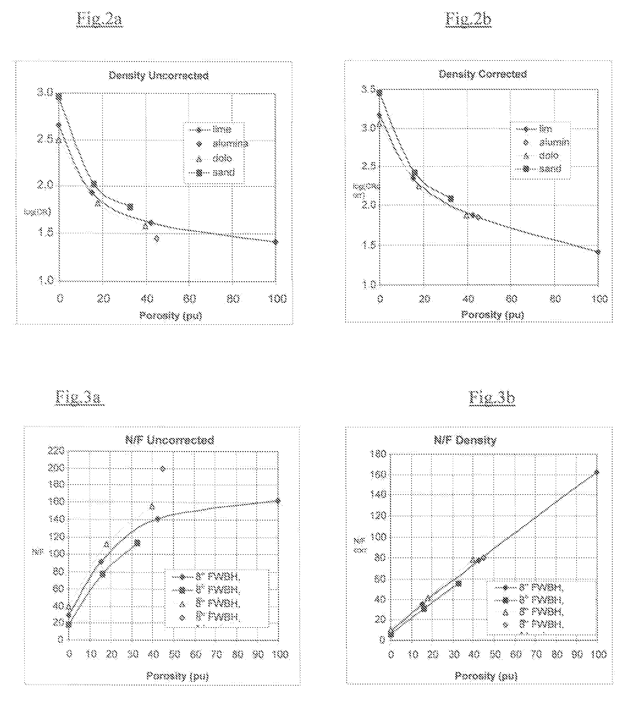
However, accuracy problems remain with these two detectors systems since the response of said neutron porosity tool significantly varies with the density of the formation to be logged.
However, this technique has various drawbacks, among which is a strong restriction on the placement of the detectors, which in turns, leads to important mechanical constraints.

Method used


Image

  • Neutron measurement method for determining porosity of a formation surrounding a borehole
  • Neutron measurement method for determining porosity of a formation surrounding a borehole
  • Neutron measurement method for determining porosity of a formation surrounding a borehole

Examples


Embodiment Construction

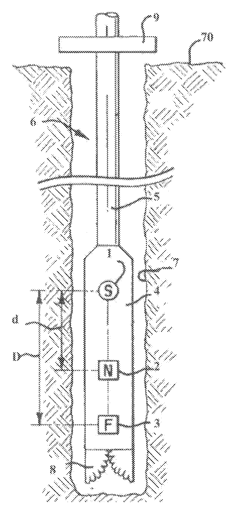
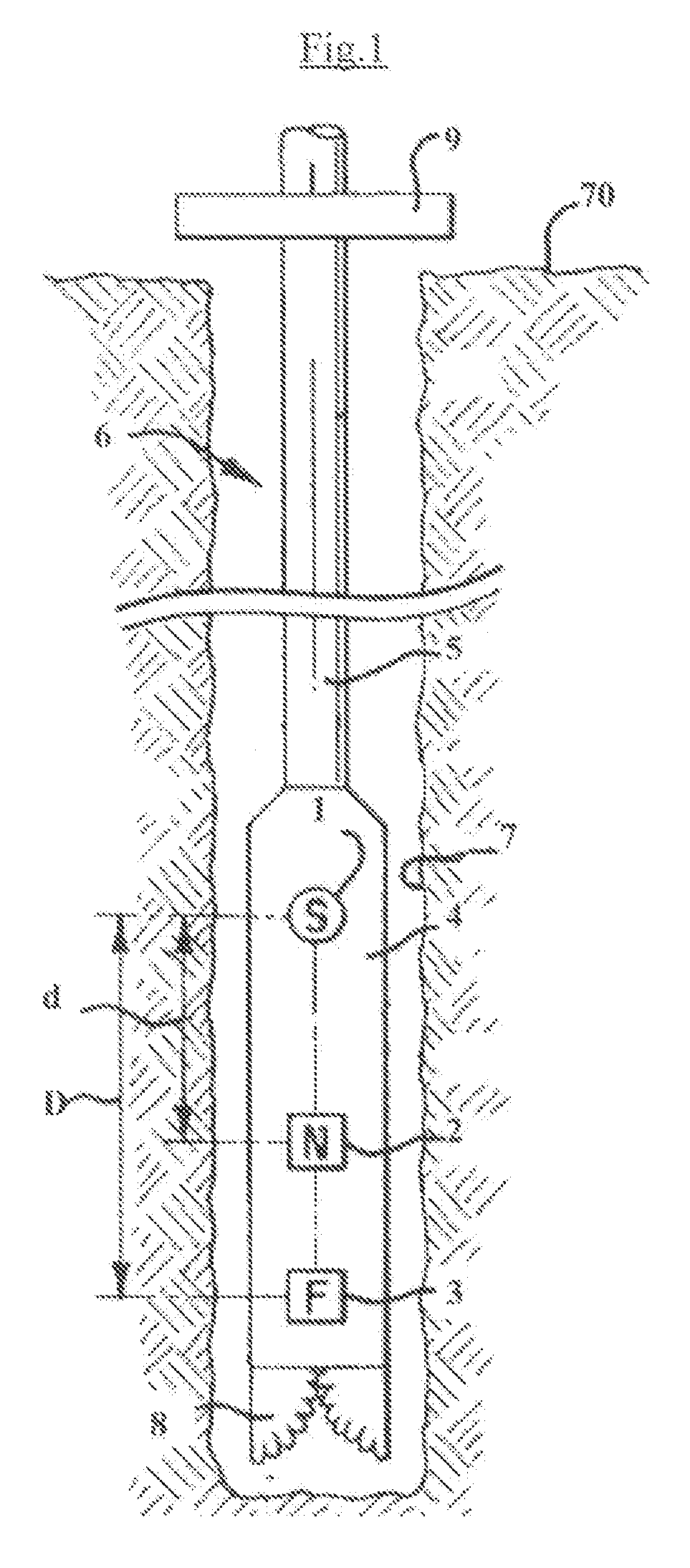
[0026]FIG. 1 illustrates a detector neutron porosity device embodied as a logging-while-drilling tool. In this example of a system according to the invention, a source of fast neutrons 1, a near detector 2 and a far detector 3 are positioned within a drill collar 4, which will be referred to as the LWD tool. In another example of a method and system according to the invention, the tool can utilize more than two axially spaced detectors, thereby allowing single or pairs of detectors responses to be selected to optimize the limits of the prospected zone. The LWD tool 4 is suspended by means of a drill string 5 within a borehole 6 penetrating an earth formation 7. The upper end of the drill string 5 is suspended at the surface of the earth 70 preferably from conventional rotary drilling draw works (not shown). A drill bit 8 is affixed to the lower end of the LWD tool. The drill string 5 is rotated by means of a kelly 9 thereby rotating the LWD tool 4 and drill bit 8, and thereby extend...


PUM


Abstract

The invention concerns a neutron measurement method for determining porosity of an earth formation surrounding a borehole comprising:conveying a tool along said borehole, wherein said tool comprises a source of neutron radiation and at least one detector axially spaced from said source;generating measured detector response for said at least one detector that is indicative of neutron radiation from said source interacting with said earth formations;operating said measured detector response with a predetermined mathematical equation and thereby obtaining corrected detector response that is independent of the density of said earth formation; anddetermining porosity of the earth formation surrounding the borehole from said corrected detector response.The invention also relates to a system implementing said method.

Description

BACKGROUND OF THE INVENTION[0001]This invention relates to the determination of a characteristic of earth formations penetrated by a borehole, and more particularly to the determination of formation porosity through neutron measurements.[0002]In hydrocarbon exploration and production, it is of prime importance to determine (a) if a given earth formation contains hydrocarbon, (b) the amount of hydrocarbon within the formation, and (c) the producibility of the hydrocarbon in place within the formation. The amount of hydrocarbon present within a formation is a function of the pore space or the “porosity” of the formation. In drilling wells for the production of hydrocarbons, it is desirable to measure the porosity of each prospective hydrocarbon producing formation penetrated by the borehole. It is even more desirable, for economic and prospective reasons to determine the porosity of prospective formations during the actual drilling of the borehole.[0003]Over the past decades, many tec...

Claims


Application Information

Patent Timeline
Patent Type & Authority Patents(United States)
IPC IPC(8): G01V5/10E21B49/00G01V5/08
CPCG01V5/108G01V5/08G01V5/10
Inventor ELLIS, DARWINCOUET, BENOITEVANS, MICHAELCASE, CHARLES R.ALLIOLI, FRANCOISE
Owner SCHLUMBERGER TECH CORP
Learn More