
Method and apparatus for adaptive digital predistortion using nonlinear and feedback gain parameters

a feedback gain and digital predistortion technology, applied in the field of amplifier nonlinearity compensation techniques, can solve problems such as the difficulty of preventing the energy transmitted by the device from spreading into adjacent channels, and the interference of devices operating on adjacent channels

Active Publication Date: 2006-09-26
AVAGO TECH INT SALES PTE LTD
View PDF18 Cites 42 Cited by
  • Summary
  • Abstract
  • Description
  • Claims
  • Application Information

AI Technical Summary

Benefits of technology

The patent describes a method and device for improving the quality of an audio signal by adjusting the distortion characteristics of an amplifier. The method involves predistorting the signal based on static coefficients that represent the non-linear distortion of the amplifier. It also uses a non-linear gain parameter to reduce errors between the input signal and a feedback signal. The non-linear gain parameter adapts the amount of distortion introduced by the predistorter based on the input voltage. The method can be implemented by multiplying the input signal by the non-linear gain parameter and then processing it using a feedback gain parameter to compensate for small-signal gain. The technical effects of this patent include improved audio quality and reduced distortion in audio signals.

Problems solved by technology

In other words, while a wireless communication device may be configured to transmit over a specific frequency channel at any given time, it is difficult to prevent the energy transmitted by the device from spreading over into adjacent channels.
If too much energy resides in the adjacent channels, then the energy can interfere with devices operating on the adjacent channels.

Method used


Image

  • Method and apparatus for adaptive digital predistortion using nonlinear and feedback gain parameters
  • Method and apparatus for adaptive digital predistortion using nonlinear and feedback gain parameters
  • Method and apparatus for adaptive digital predistortion using nonlinear and feedback gain parameters

Examples


Embodiment Construction

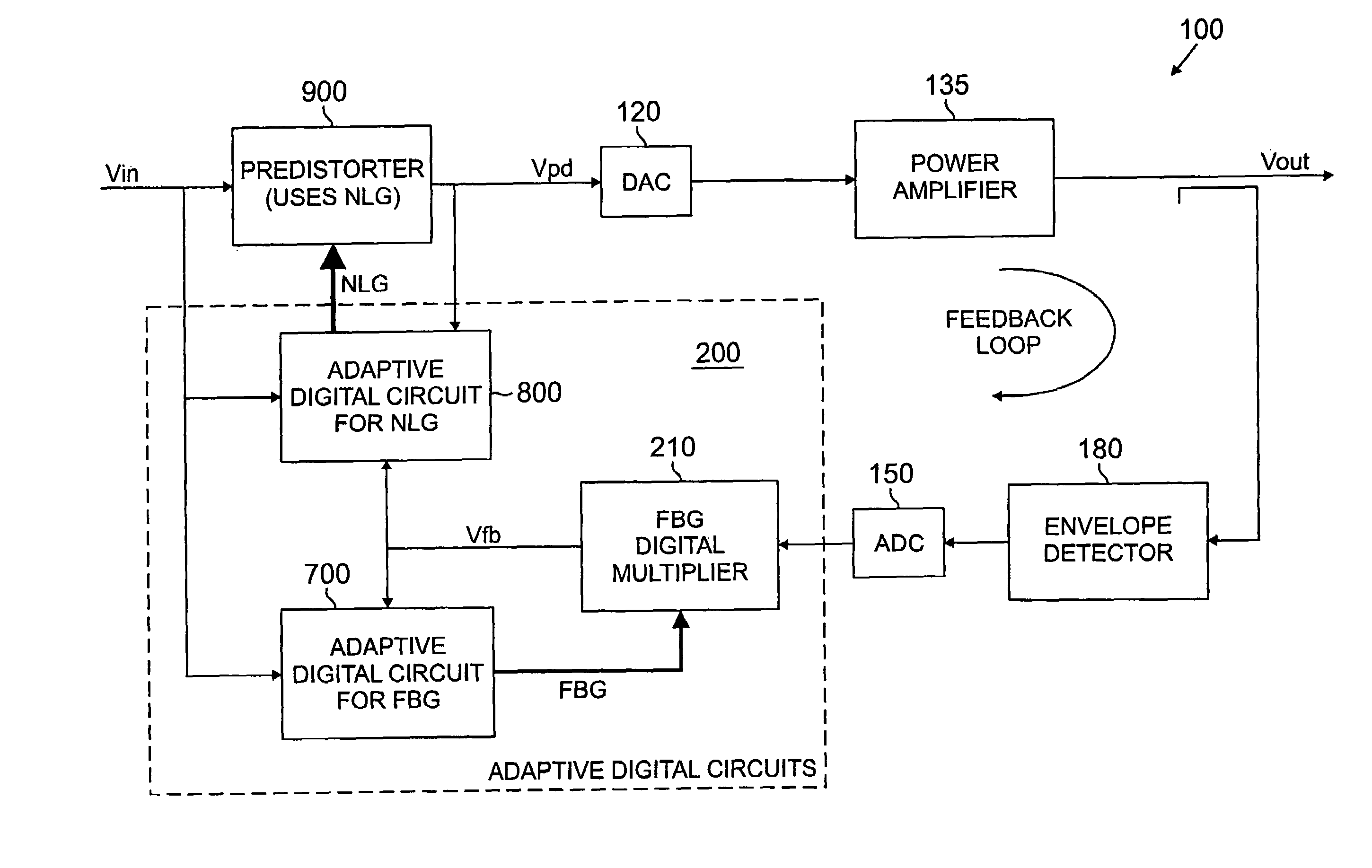
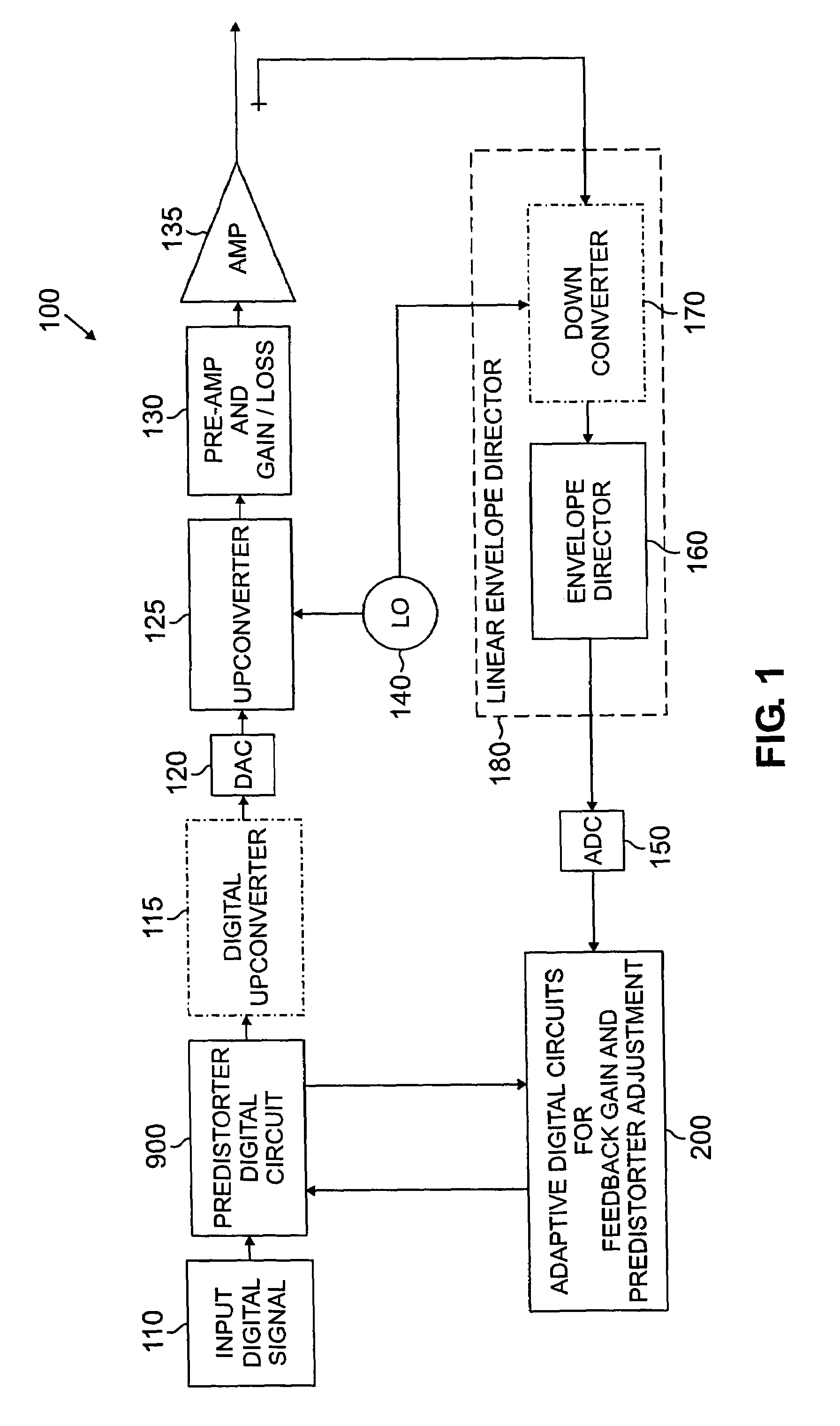
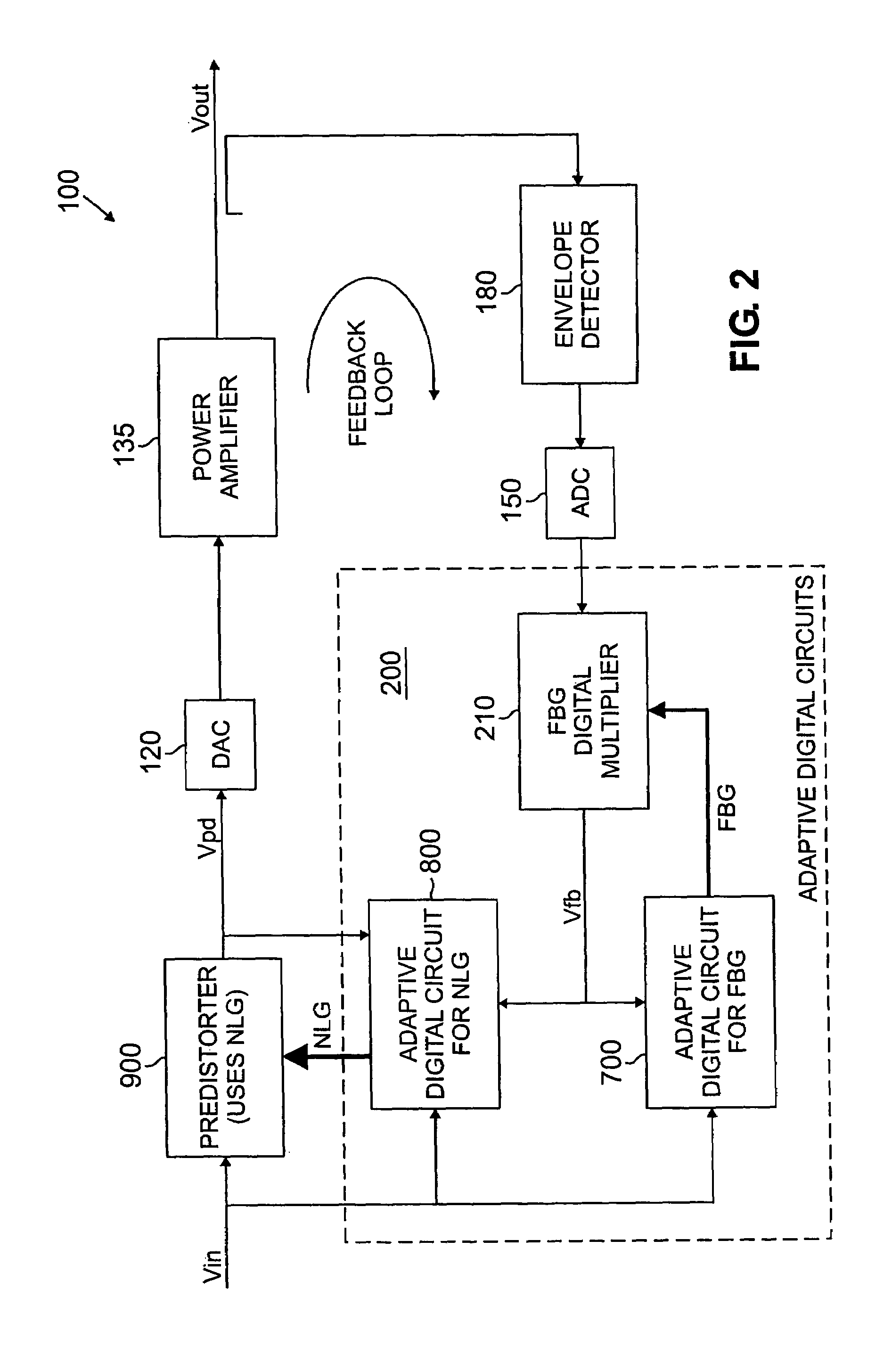
[0019]FIG. 1 is a schematic block diagram of a predistortion amplification system 100 incorporating features of the present invention. As shown in FIG. 1, the predistortion amplification system 100 receives a digital input signal 110 that is applied to a predistorter 900, discussed further below in conjunction with FIG. 6, and an optional digital upconverter 115. The upconverted digital signal is then converted to an analog system by a digital-to-analog converter 120.

[0020]The analog signal is applied to another upconverter 125 that modulates the analog signal using a local oscillating frequency outputted from a local oscillator 140. The signal is preamplified at stage 130 to achieve a desired gain or loss before being applied to the primary amplifier 135. The amplifier 135 generates an amplified output signal and typically transmits it to a transmission antenna (not shown).

[0021]The amplified output signal from the output of the amplifier 135 is also applied in a feedback loop to a...


PUM


Abstract

A predistorter is disclosed that predistorts an input signal based on one or more static coefficients that are representative of a non-linear distortion characteristic of an amplifier. The input signal is also processed based on a non-linear gain parameter that reduces an error metric between the input signal and a feedback signal. The nonlinear gain parameter adapts an amount of nonlinearity introduced by the predistorter. The non-linear gain adaptation is performed, for example, when the input voltage is above a threshold input voltage. The input signal can be processed by multiplying the input signal by the non-linear gain parameter followed by table-coefficient processing, or by both multiplying the input by the non-linear gain parameter followed by dividing the table-coefficient processed output signal by the same non-linear gain parameter. The input signal can also be processed based on a feedback gain parameter that compensates for a small-signal gain of the feedback loop. The feedback gain parameter attempts to maintain a small-signal gain of approximately unity.

Description

FIELD OF THE INVENTION[0001]The present invention relates generally to techniques for compensating for non-linearities in amplifiers, and, more particularly, to adaptive digital predistortion techniques.BACKGROUND OF THE INVENTION[0002]Communication devices must comply with various emission requirements and other spectrum constraints defined by a number of regulatory bodies, such as the Federal Communications Commission (FCC) in the United States, or communication standards, such as the IS-95 Base Station Emission Requirements, defined in TIA / EIA-95-B, “Mobile StationBase Station Compatibility Standard for Wideband Spread Spectrum Cellular Systems,” Section 7—Requirements for Base Station CDMA Operation. Adjacent Channel Power Ratio (ACPR), for example, is one such constraint that is generally defined as the ratio of the average power in the adjacent frequency channel to the average power in the transmitted frequency channel. In other words, while a wireless communication device ma...

Claims


Application Information

Patent Timeline
Patent Type & Authority Patents(United States)
IPC IPC(8): H03F1/26H03F1/32
CPCH03F1/3247H03F1/3294H03F1/3258H03F1/3252
Inventor MOFFATT, JAMES P.SAUNDERS, JEFFREY H.
Owner AVAGO TECH INT SALES PTE LTD
Learn More