Intelligent locking system

a locking system and intelligent technology, applied in the field of locking systems, can solve the problems of maintenance and security problems, keys must be used to operate, and the vendor/owner cannot always account for the correct amount of cash, so as to avoid time-wasting and demeaning effects

Inactive Publication Date: 2006-09-26
TYPHOON INDS
View PDF10 Cites 27 Cited by
  • Summary
  • Abstract
  • Description
  • Claims
  • Application Information

AI Technical Summary

Benefits of technology

[0014]Another advantage of the present invention is that it enables a user to identify the location of his or her stored articles when the user has forgotten his or her locker number. In accordance with certain preferred embodiments of the present invention, users will be able to walk up to a terminal and apply a fingertip. A central computer, which will have recorded the details of all recent users, will note the details of the fingertip, compare the fingertip with its records and then tell the user which locker is theirs. This feature will avoid the time-wasting and demeaning process of trying to open hundreds of lockers in order to identify the right one.
[0015]In certain preferred embodiments, the present invention utilizes an intelligent locking device, referred to by the assignee as a SmartLok, having a credit card sized printed circuit board. The intelligent locking device may be substituted wherever keys, barrels and non-intelligent electronic locks have traditionally been used. Unlike other electromechanical or electronic locks, the intelligent locking device of the present invention utilizes a printed circuit board that incorporates a powerful on-board microprocessor. The microprocessor is programmable so that it may be modified to satisfy an operator's particular locking and opening requirements. For example, an operator of a locking system in an airport or train station may have different operating requirements than an operator in a school environment (e.g. the airport operator may want to change money while the school operator may want the system to be free). In certain embodiments, the locking system includes a plurality of intelligent locking devices, the printed circuit board of each intelligent locking device being able to communicate with the printed circuit boards of the other intelligent locking devices and with a central controller, referred to by the assignee as a Customer Service Station (CSS), such as a Microsoft Windows NT supervisory systems. It is contemplated that the present invention may be distributed over a wide geographic area and may be managed locally or remotely. Industry standard communications are supported ranging from UTP interconnect for local infrastructure to high-speed modem and Internet protocols for remote access.
[0016]The printed circuit board of each intelligent locking device is preferably a credit card size printed circuit board containing the software necessary to offer the world's first true self-intelligent lock controller. Contained within the printed circuit board of each intelligent locking device is a multi-function processor chip, having both RAM and Flash memory as well as processing power. The chip is programmed to operate a number of onboard devices concerned with the control and monitoring of a motor driven lock mechanism. Specifically, each intelligent locking device preferably includes a solid state motor driver chip, a voltage regulator chip, two sets of gear drive status sensors and a pair of two color LED indicator lamps. The printed circuit board of each intelligent locking device may be programmed to communicate via an onboard network chip down a standard UTP network, back to a controller, such as a personal computer PC based operating on a Windows Operating Platform. Operational data may be downloaded to the printed circuit board of the intelligent locking device which will allow it to operate with the chosen environment independently of all other intelligent locking devices on the same network and independently of the controller. During initial setup, the intelligent locking device is given instructions from the central controller. After initial setup, the intelligent locking device runs independently. The intelligent locking device then communicates with the central controller for additional information and / or authorization as required. The PCB-based intelligent locking device is capable of independent security and monitors the mechanical lock assemblies associated therewith. An unauthorized change of status will cause the printed circuit board of the intelligent locking device to broadcast an alarm state to the controller for further action. Meanwhile, the intelligent locking device will take preventive preset action to protect its one or more secured enclosures.
[0017]In other preferred embodiments, the present invention includes an intelligent locking device for selectively locking and unlocking one or more enclosed areas including a housing having a microprocessor for operating the intelligent locking device, at least one bolt slidably mounted to the housing and movable between a retracted position and an extended position, and a mechanical driving mechanism in contact with the slidable bolt for moving the bolt between the retracted and extended positions, the driving mechanism being in communication with the microprocessor for receiving signals for retracting and extending the bolt.
[0018]The system may use a Distributed Lock Protocol (SDLP), which is a proprietary protocol designed to operate a Controller Area Network (CAN) merging to 2.0a and 2.0b environment. The protocol is used to communicate locking and programmatic control states and acts between intelligent locking device processes and intelligent locker Customer Service Station (CSS) software processes. The state and act model is embedded within the intelligent locker controller software and CSS CAN DLL routines. The protocol is implemented by these same routines.
[0019]SDLP is preferably a message-based protocol with fixed field definitions conforming to the CAN 2.0a specification. The protocol relies on the persistence and model of CAN to provide a reliable transport. The protocol embraces many functions, including setting controller specific parameters, controller state checking functions and an acknowledgment model for operational locking functions.

Problems solved by technology

There are a number of problems associated with mechanical locking systems that require a user to pay to use the system.
These problems include the fact that each locker may only accept a limited number of coins, and those coins are the only acceptable method of payment.
As a result, a third party must collect the coins from the system and the vendor / owner cannot always account for the correct amount of cash.
Another problem with mechanical lockers is that keys must be used to operate them.
These keys are commonly lost or stolen, thereby creating maintenance and security problems.
In the early 1990's, MORS Industries experienced problems and sold the electronic locker division to a Dutch company operating under the name Logibag SA.
Although Logibag SA has a large number of lockers in place, its electronic lockers use out-dated technology, and each locker has a relatively high selling price of approximately $1,000–$1,200 per locker.
Although there are currently about 12,000 Loksafe lockers installed worldwide, Loksafe uses 1980's DOS-based programming and therefore has a limited ability to accept upgrades.
Like Logibag, Loksafe has a high per unit cost and requires special maintenance and support.
Although K W Muller uses PC based technology, its system has proven to be unreliable and difficult to use.
The Eurolocker system has an unreliable electronic system.
As a result, Eurolocker has enjoyed only limited success.
In fact, there have been many negative responses to the quality of Eurolocker, and the system is unlikely to be used in any major terminals or similar locations.
However, this attempt failed.
American Locker Security Systems then obtained the United States dealership for Loksafe, but achieved only marginal success due to the high price of the Loksafe units in the United States.
Since then, American Locker Security Systems has attempted to develop its own electronic system, but has been unsuccessful.

Method used


Image

  • Intelligent locking system
  • Intelligent locking system
  • Intelligent locking system

Examples


Embodiment Construction

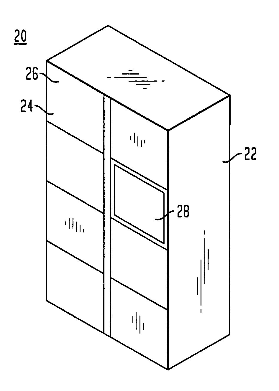
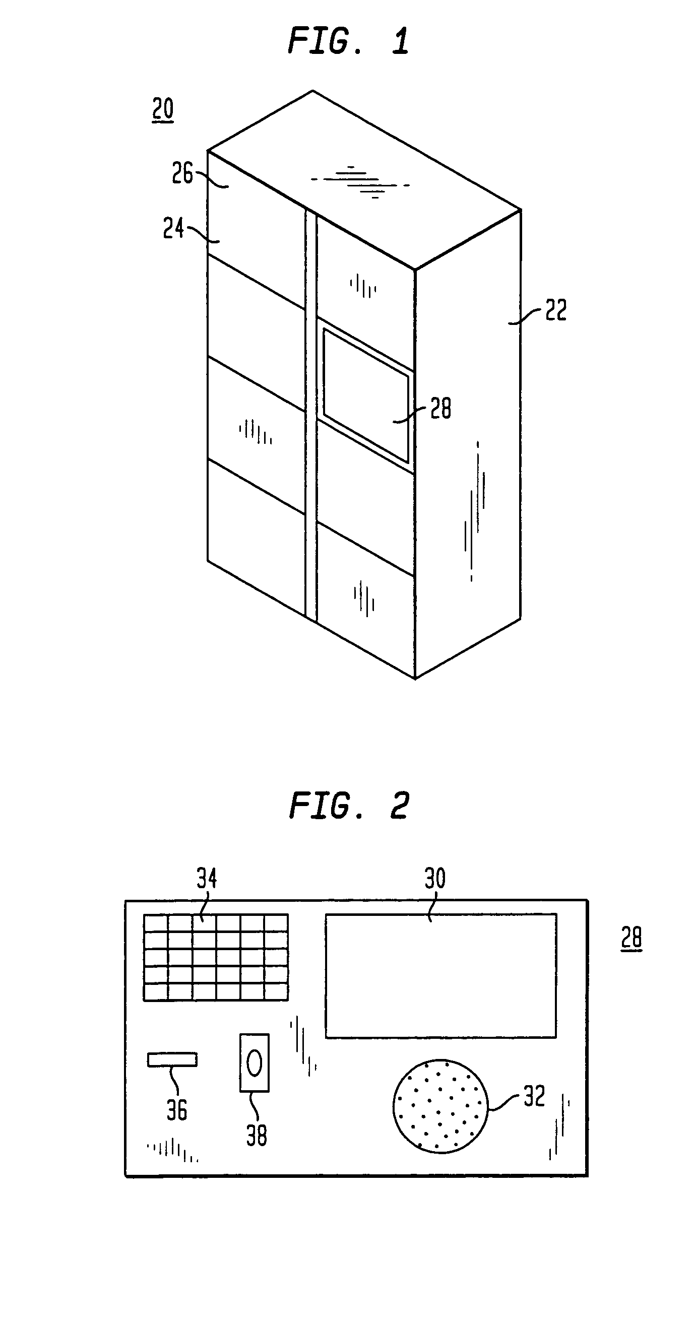
[0034]FIG. 1 shows a perspective view of an intelligent locker system, in accordance with certain preferred embodiments of the present invention. The intelligent locker system 20 includes a cabinet 22 having a plurality of locker openings 24. Each opening 24 is covered by a door 26 hingedly connected to the cabinet. The intelligent locker system also includes a central controller, commonly referred to by the assignee as a Customer Service Station (CSS) 28. In the particular embodiment shown in FIG. 1, the intelligent locker system includes two vertically-extending columns of locker openings, each column having a series of vertically aligned openings. In the particular embodiment shown, the locker system has a first column of four locker openings, and a second column of three locker openings and one Customer Service Station. The capacity of the locker system may be increased by adding another locker cabinet 22 to the left or right of that shown in FIG. 1. Thus, additional locker cabi...


PUM


Abstract

A method of using an electronic locking system to access one of a plurality of lockers includes programming the system by recording at least one biometric characteristic of a user, storing the recorded biometric characteristic of the user in memory, and associating the recorded biometric characteristic of the user with one of the lockers so that the user is authorized to access the locker. The method also includes locking the locker, re-recording the biometric characteristic of the user, after the re-recording step, comparing the re-recorded biometric characteristic of the user with the recorded biometric characteristic of the user and unlocking the locker if the re-recorded biometric characteristic of the user matches the recorded biometric characteristic of the user. The system is newly reprogrammed for each subsequent user of the locker.

Description

CROSS REFERENCE TO RELATED APPLICATIONS[0001]The present application is a continuation of U.S. application Ser. No. 09 / 896,595 filed Jun. 29, 2001 now U.S. Pat. No. 6,806,807 and claims benefit of U.S. Provisional Application No. 60 / 215,218 filed Jun. 30, 2000, the disclosures of which are hereby incorporated by reference herein.FIELD OF THE INVENTION[0002]The present invention is directed to a locking system for securing articles in lockable storage containers and is more particularly is directed to an electronic locking system that uses one or more microprocessors for identifying authorized users of the system, and for granting access to the one or more storage containers associated with each authorized user.BRIEF DESCRIPTION OF THE PRIOR ART[0003]Mechanical lockers are used in both concessional and non-concessional venues. In concessional venues, such as airports, bus and train stations, malls, theme parks and ski resorts, users must often pay to use the lockers. In non-concessio...

Claims


Application Information

Patent Timeline
Patent Type & Authority Patents(United States)
IPC IPC(8): H04Q9/00G06K9/00B65D55/14F16C32/06G05B23/00G06F7/00G06F7/04G07C9/00
CPCG07C9/00087G07C9/00103G07C2011/02Y10T70/5031G07C9/257G07C9/27
Inventor CAYNE, JORDANADAMS, MARKMACALPINE, COLINLAIDLAW, ROBERTTHOMAS, LAURENCE
Owner TYPHOON INDS
Why Eureka
Try Eureka