Scintillation tolerant optical field sensing system and associated method

a sensing system and optical field technology, applied in the field of optical field sensing systems and methods, can solve the problem that the measurement obtained by the wavefront sensor and/or the intensity sensor generally has at least some nois

Active Publication Date: 2006-09-26
THE BOEING CO
View PDF9 Cites 17 Cited by
  • Summary
  • Abstract
  • Description
  • Claims
  • Application Information

AI Technical Summary

Benefits of technology

[0009]An optical field sensing system and an associated method are provided by the embodiments of the present invention that are tolerant of scintillation. As such, the optical field sensing system and method of embodiments of the present invention accurately determine the phase of an optical wavefront, even in instances in which the optical wavefront is scintillated. As such, the optical field sensing system and method of the present invention can provide appropriate wavefront compensation, such as by appropriately shaping a deformable mirror and / or appropriately processing the signals representative of the optical wavefront, such that the wavefront measurements suffer less, if any, degradation due to scintillation than that associated with conventional optical sensing systems.

Problems solved by technology

The measurements obtained by the wavefront sensor and / or the intensity sensor generally have at least some noise.

Method used


Image

  • Scintillation tolerant optical field sensing system and associated method
  • Scintillation tolerant optical field sensing system and associated method
  • Scintillation tolerant optical field sensing system and associated method

Examples


Embodiment Construction

[0020]The present invention now will be described more fully hereinafter with reference to the accompanying drawings, in which preferred embodiments of the invention are shown. This invention may, however, be embodied in many different forms and should not be construed as limited to the embodiments set forth herein; rather, these embodiments are provided so that this disclosure will be thorough and complete, and will fully convey the scope of the invention to those skilled in the art. Like numbers refer to like elements throughout.

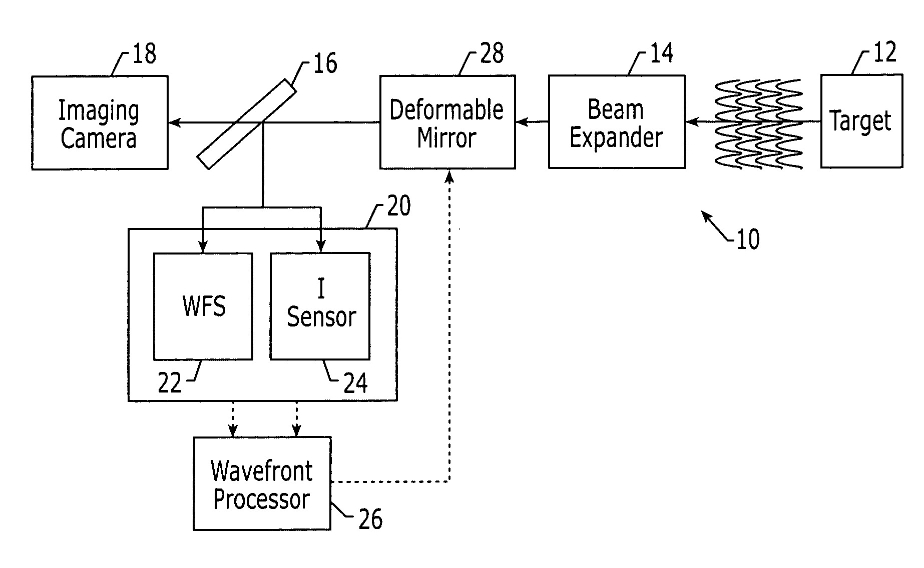
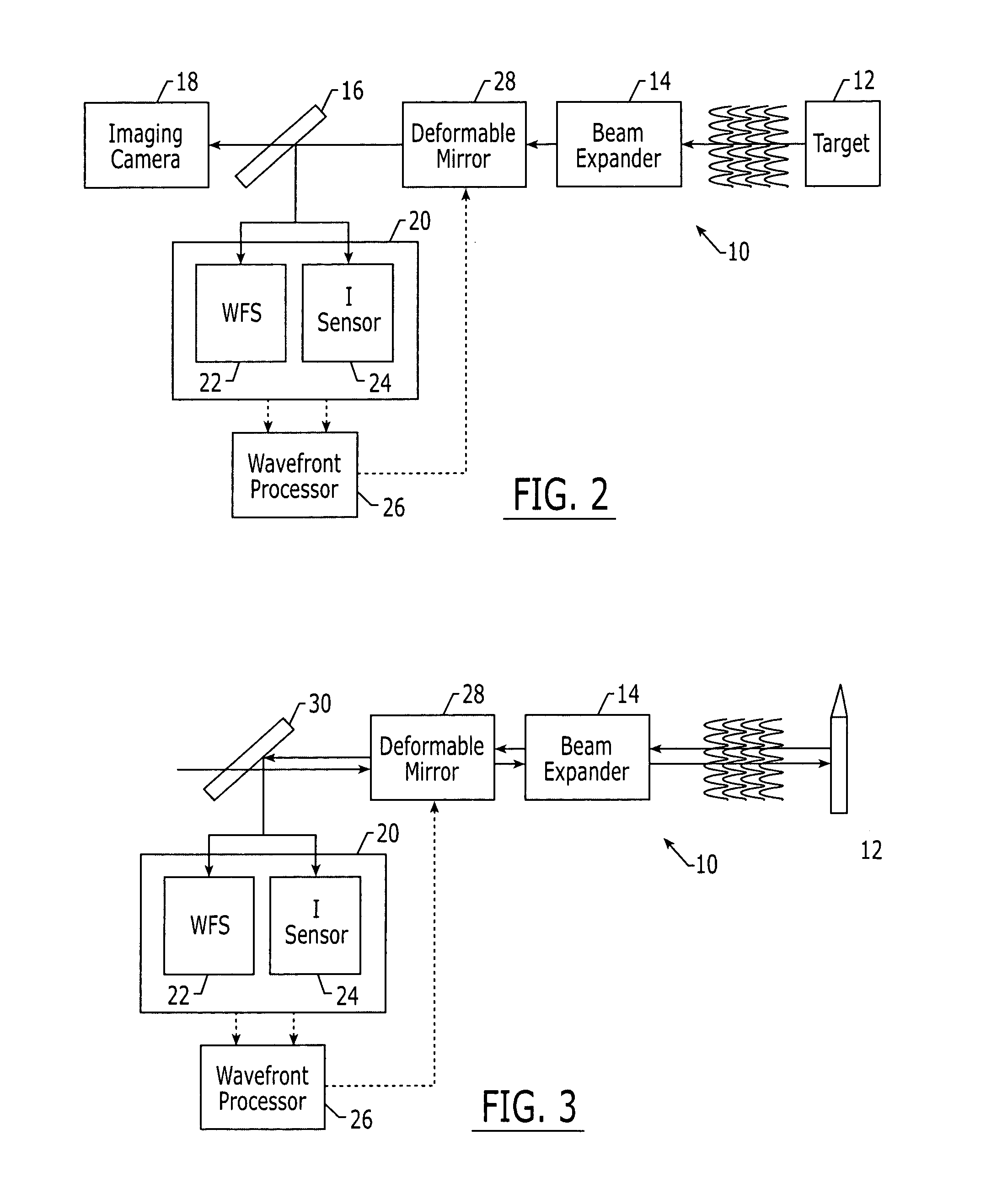
[0021]An optical field sensing system 10 of the present invention can be utilized to determine the phase of an optical wavefront for a wide variety of applications. For example, the optical field sensing system may be utilized in conjunction with an imaging system as shown in FIG. 2. Alternatively, the optical field sensing system could be utilized in conjunction with directed energy weapons, such as high energy lasers and the like, as shown in FIG. 3. Sti...


PUM


Abstract

An optical field sensing system and an associated method are provided that are tolerant of scintillation. The system includes a wavefront sensor that measures gradients across a wavefront at a first resolution defined by the subapertures of the wavefront sensor. The system also includes an intensity sensor that measures the intensity across the wavefront at a higher resolution. The system further includes a wavefront processor that determines respective phases across the wavefront. In addition to the gradients and the intensity measurements, the wavefront processor may determine the respective phases based also upon the noise affiliated with the measurements. In this regard, the wavefront processor may determine the respective phases across the wavefront at least partially based upon the gradients as adjusted by weights that are based upon the intensity measured by the intensity sensor and are influenced by evidence of scintillation.

Description

FIELD OF THE INVENTION[0001]The present invention relates generally to optical field sensing systems and methods and, more particularly, to optical field sensing systems and methods that are tolerant of scintillation so as to continue providing accurate estimates of a wavefront that is experiencing scintillation.BACKGROUND OF THE INVENTION[0002]Wavefront detection and analysis are desirable for many applications. For example, telescopes and other optical sensing systems desirably measure an optical wavefront in an accurate fashion. Additionally, directed energy weapons, such as high energy lasers and the like, often require an associated optical sensing system for detecting the optical wavefront returning from a target. In addition to astronomy and directed energy weapons systems, a number of other applications utilize or will utilize optical wavefront detection including scientific measurement systems, optical communications systems (such as those utilizing free space lasers) and m...

Claims


Application Information

Patent Timeline
Patent Type & Authority Patents(United States)
IPC IPC(8): G01J1/42G01B9/02G01J1/20G01J1/00G01J9/00G02B26/06
CPCG02B26/06G01J9/00
Inventor GERWE, DAVID RODERICKSCHALL, HAROLD BARRYSTONE, JAMES PRESTON
Owner THE BOEING CO
Why Eureka
Try Eureka