Apparatus and method for input channel isolation within an electronic test instrument

a technology of electronic test instruments and input channels, applied in the direction of substation equipment, instruments, transmission monitoring, etc., can solve the problems of high cost, difficult linearization of optocouplers, and high cost of wide-band linear transformers

Inactive Publication Date: 2006-09-26
TEKTRONIX INC
View PDF18 Cites 15 Cited by
  • Summary
  • Abstract
  • Description
  • Claims
  • Application Information

AI Technical Summary

Benefits of technology

[0004]These and other deficiencies of the prior art are addressed by the present invention of a method and apparatus enabling the isolation of wide band signals in a manner avoiding the “two path scheme” and its inherent difficulties. One embodiment comprises an electrical isolation device (isolator) wherein a signal to be electrically isolated is mixed with a carrier signal by a multiplier to produce a modulated carrier signal which is passed through an isolation barrier and demodulated and filtered to extract thereby the initial input signal.

Problems solved by technology

Unfortunately, optocouplers are difficult and expensive to linearize, and wide band linear transformers are expensive.
Additionally, it is difficult to insure that the resulting isolated low end high frequency signal components of the signals under test are sufficiently well matched such that they may be recombined to produce a “flat” signal suitable for further processing by the test and measurement device.

Method used


Image

  • Apparatus and method for input channel isolation within an electronic test instrument
  • Apparatus and method for input channel isolation within an electronic test instrument
  • Apparatus and method for input channel isolation within an electronic test instrument

Examples


Embodiment Construction

[0011]The subject invention will be primarily described within the context of test and measurement devices such as digital storage oscilloscopes, analog oscilloscopes and the like. However, it will be appreciated by those skilled in the art that the invention may be advantageously employed in any environment where electrical isolation of a relatively wide bandwidth signal is desired.

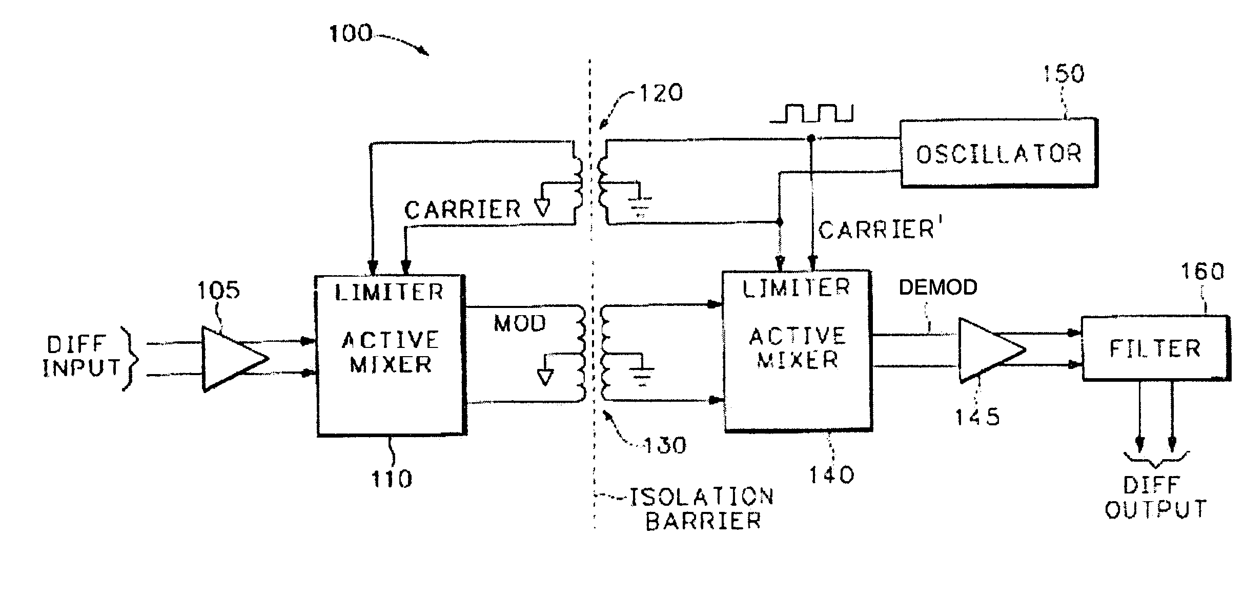
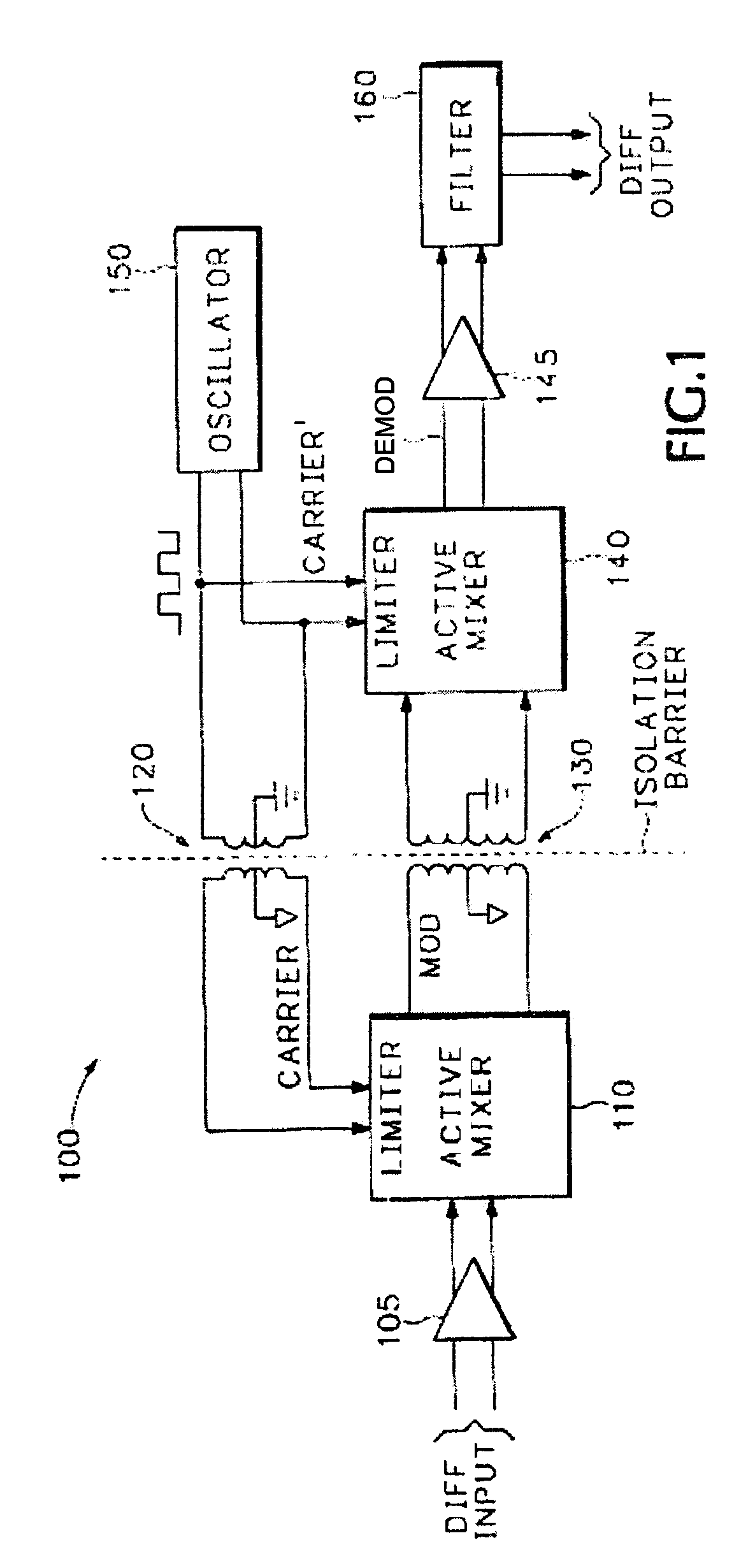
[0012]FIG. 1 depicts a high level block diagram of a signal isolation system according to an embodiment of the invention. Specifically, the system 100 of FIG. 1 comprises a first buffering device 105, a first active mixer 110, a first isolating device 120, a second isolating device 130, a second active mixer 140, a second buffering device 145, an oscillator 150 and a filter 160. It is noted that the first buffering device 105 and first mixer 110 are electrically isolated from the second active mixer 140, second buffering device 145, oscillator 150 and filter 160.

[0013]The system 100 receives a differenti...


PUM


Abstract

An electrical isolation device wherein a signal to be electrically isolated is mixed with a carrier signal by a multiplier to produce a modulated carrier signal which is passed through an isolation barrier and demodulated and filtered to extract thereby the initial input signal.

Description

FIELD OF THE INVENTION[0001]The invention relates generally to signal analysis devices and, more particularly, to a method and apparatus for providing electrical isolation such as between a signal under test (SUT) and an electronic testing device.BACKGROUND OF THE INVENTION[0002]Signal acquisition devices or test and measurement devices such as digital storage oscilloscopes (DSOs) and the like receive one or more signals under test (SUT) via one or more respective input channels. It is important that the input channels be electrically isolated from each other and from the chassis ground of the test and measuring device. Such isolation is necessary for signals having a frequency from DC to the bandwidth of the measuring device. Such isolation allows multiple signals under test to be provided to, and analyzed by, the same measuring device without affecting the systems / signals under test.[0003]One isolation method known to those skilled in the art for use in wide bandwidth systems is t...

Claims


Application Information

Patent Timeline
Patent Type & Authority Patents(United States)
IPC IPC(8): H04B1/38G01R19/00H04B5/00H04L1/24
CPCH04L1/24H04B5/005
Inventor EASTWOOD, JAMES S.
Owner TEKTRONIX INC
Why Eureka
Try Eureka