
Method and apparatus for maximizing test coverage

a test coverage and test technology, applied in the field of computer software, can solve the problems of background art that background art does not teach or suggest a method for increasing such functional coverage, background art does not teach or suggest a method for performing, etc., to achieve the effect of improving test coverage and improving test coverag

Inactive Publication Date: 2006-09-26
CADENCE DESIGN ISRAEL II
View PDF9 Cites 48 Cited by
  • Summary
  • Abstract
  • Description
  • Claims
  • Application Information

AI Technical Summary

Benefits of technology

"The present invention is a method and system for automatically improving the coverage of tests for a device under test (DUT) by identifying coverage holes, modifying the input process to test those areas, and iteratively adjusting the performance of the test to obtain increasingly better functional coverage. The method and system can also learn from previous tests to increase coverage and improve the efficiency of the testing process. The technical effects of the invention include improved test coverage, reduced time and effort for users, and improved automation of the testing process."

Problems solved by technology

The background art does not teach or suggest a method for maximizing coverage of tests for the DUT by targeting automatically discovered functional coverage goals.
In addition, the background art does not teach or suggest a method for increasing such functional coverage which is both unaffected by the size of the DUT state space and is applicable to any class of DUT.
Furthermore, the background art does not teach or suggest a method for performing the types of “brute force” tests with crosses between many boundary conditions which users could perform manually, but which they do not have the time or patience to perform.
Also, the background art does not teach or suggest a method for iteratively and automatically adjusting the performance of any such method for performing functional tests for obtaining increasingly better functional coverage automatically.

Method used


Image

  • Method and apparatus for maximizing test coverage
  • Method and apparatus for maximizing test coverage
  • Method and apparatus for maximizing test coverage

Examples


Embodiment Construction

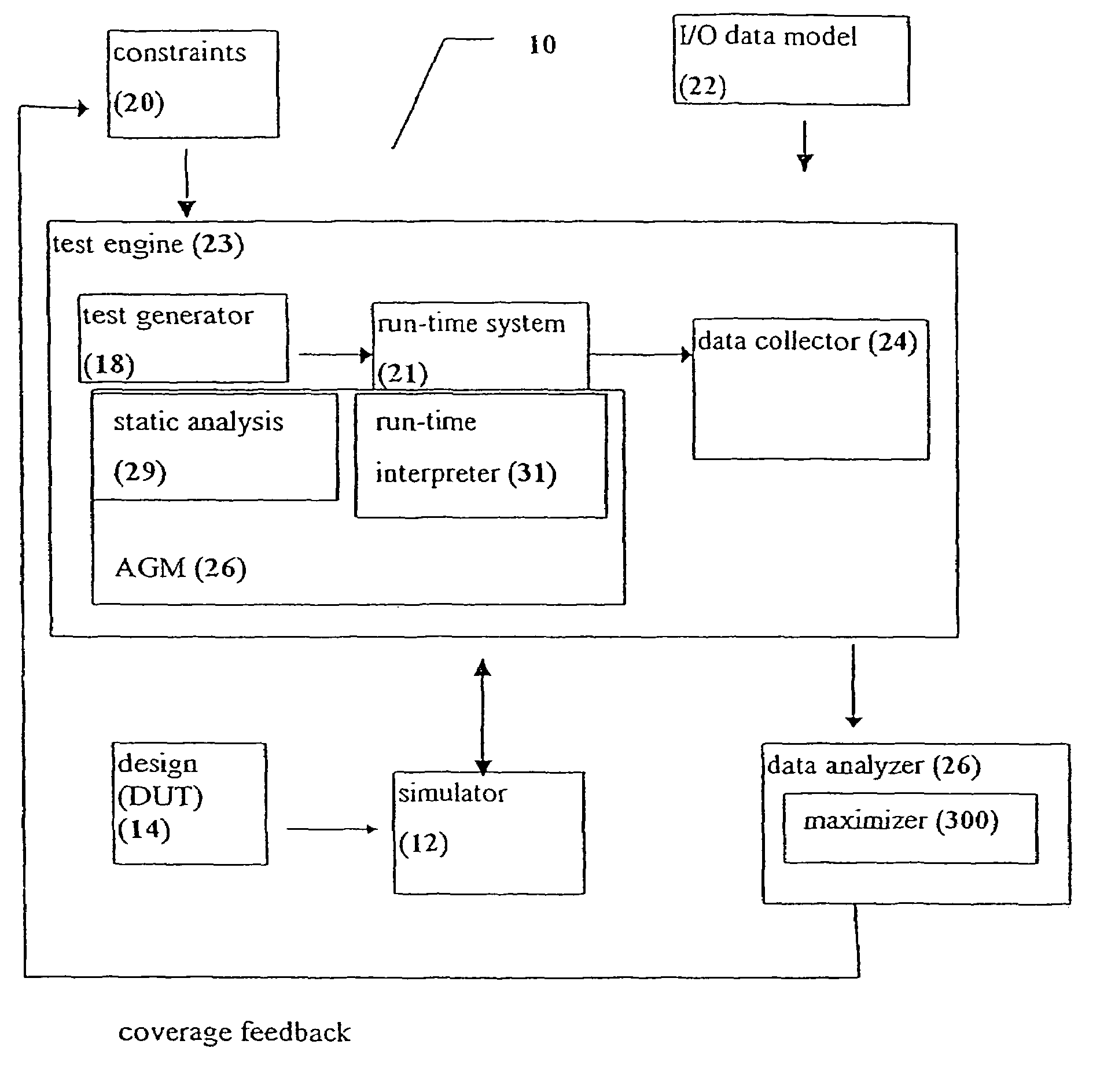
[0034]The present invention improves test coverage by identifying coverage holes, modifying the input process to test those areas, then repeating the process iteratively to continue to improve test coverage.

[0035]The method of the present invention preferably starts with a user-generated test, from which the coverage information is more preferably extracted, for example from the environment architectural files, and / or from other existing sources of coverage and testing information. Such information optionally and preferably includes coverage groups, items and buckets. Additionally, coverage information is preferably extracted from the DUT implementation. Next, the test is run and the results are analyzed. Coverage holes are then automatically detected and targeted by augmenting the test, optionally with additional constraints. The method of the present invention optionally and most preferably does not alter the user's original test, but instead adds constraints to a separate version...


PUM


Abstract

A method and an apparatus for determining functional coverage of a design for a device under test (DUT), the design being encapsulated in a DUT circuit design specification, in a test environment during a design test verification process.The method and apparatus utilize a coverage metric constructed from a plurality of coverage items. A first step involves obtaining a coverage group from the DUT design, for examining during the design test verification process. The coverage group includes at least one functional coverage item. Then, a set of input values is provided to the design test verification process. Next, design test verification process is performed with the set of input test values to obtain a value for each coverage item.Next step involves examining obtained coverage by comparing the value obtained from each coverage item with a coverage goal. Finally, the set of input test value is automatically altered in accordance with the examination of the obtained coverage.

Description

CROSS REFERENCE TO RELATED APPLICATIONS[0001]This application is a continuation in part of, commonly assigned U.S. patent application Ser. No. 09 / 327,966, entitled “System and Method for Measuring Temporal Coverage Detection”, filed Jun. 8, 1999, now U.S. Pat. No. 6,675,138, and incorporated herein in full by reference. This application also is a continuation in part of U.S. Application Ser. No. 60 / 208,822, entitled “Method and Apparatus for Maximizing Test Coverage”, filed Jun. 2, 2000 and incorporated herein in full by reference.FIELD OF THE INVENTION[0002]This invention relates to computer software, more particularly to computer software for analyzing the functionality of a circuit design and for analyzing the functional correctness of the circuit design.BACKGROUND OF THE INVENTION[0003]The field of electronic design automation (EDA) is well established. A number of software tools are used to describe a circuit at various levels of granularity or specificity. Such tools include g...

Claims


Application Information

Patent Timeline
Patent Type & Authority Patents(United States)
IPC IPC(8): G01R31/28G06F17/50G01R31/317G01R31/3183
CPCG01R31/31835G01R31/31707
Inventor NOY, AMOS
Owner CADENCE DESIGN ISRAEL II
Learn More