Engine cover puller

a technology of engine cover and puller, which is applied in the direction of crowbars, liquid handling, manufacturing tools, etc., can solve the problems of engine cover deformation, engine cover deformation, and engine cover deformation, so as to reduce or eliminate the damage to the sealing surface, facilitate the separation, and reduce or eliminate the deformation of the engine cover

Inactive Publication Date: 2006-10-03
HONDA MOTOR CO LTD
View PDF49 Cites 9 Cited by
  • Summary
  • Abstract
  • Description
  • Claims
  • Application Information

AI Technical Summary

Benefits of technology

[0001]The present invention relates to a device for facilitating the separation and removal of an engine cover from a sealing surface on an engine. The present invention may reduce or eliminate the deformation of an engine cover ...

Problems solved by technology

This can result in damage to the sealing surfaces between the cover and the engine.
And, on other occasions, the damage to the sealing surfaces during the removal of the cover results in the required replacement of one or more parts in order to obtain a seal between a cover and an engine.
While such materials are adequate for their installed function as a cover, the covers may be susceptible to damage during removal operations such as described previously.
In addition to sealing surface damage as described above, typical damage to the covers may include pe...

Method used


Image

  • Engine cover puller
  • Engine cover puller
  • Engine cover puller

Examples


Embodiment Construction

)

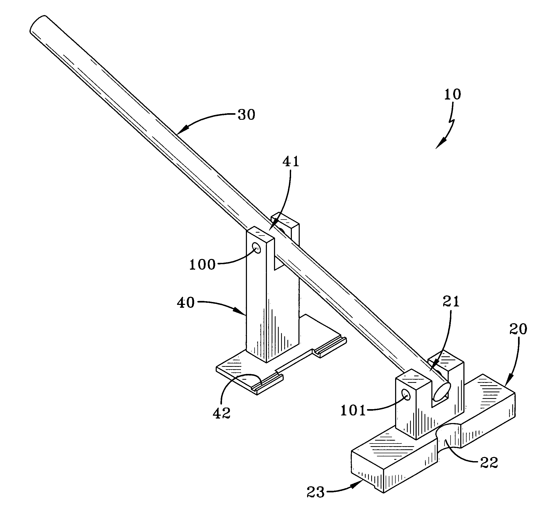
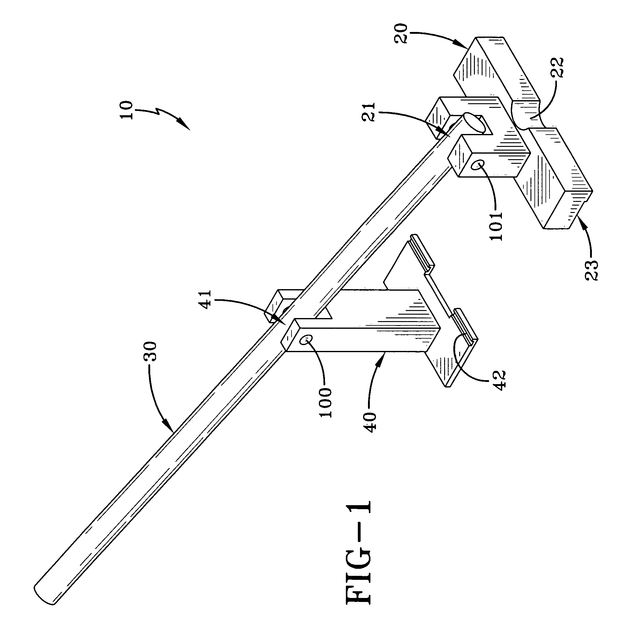
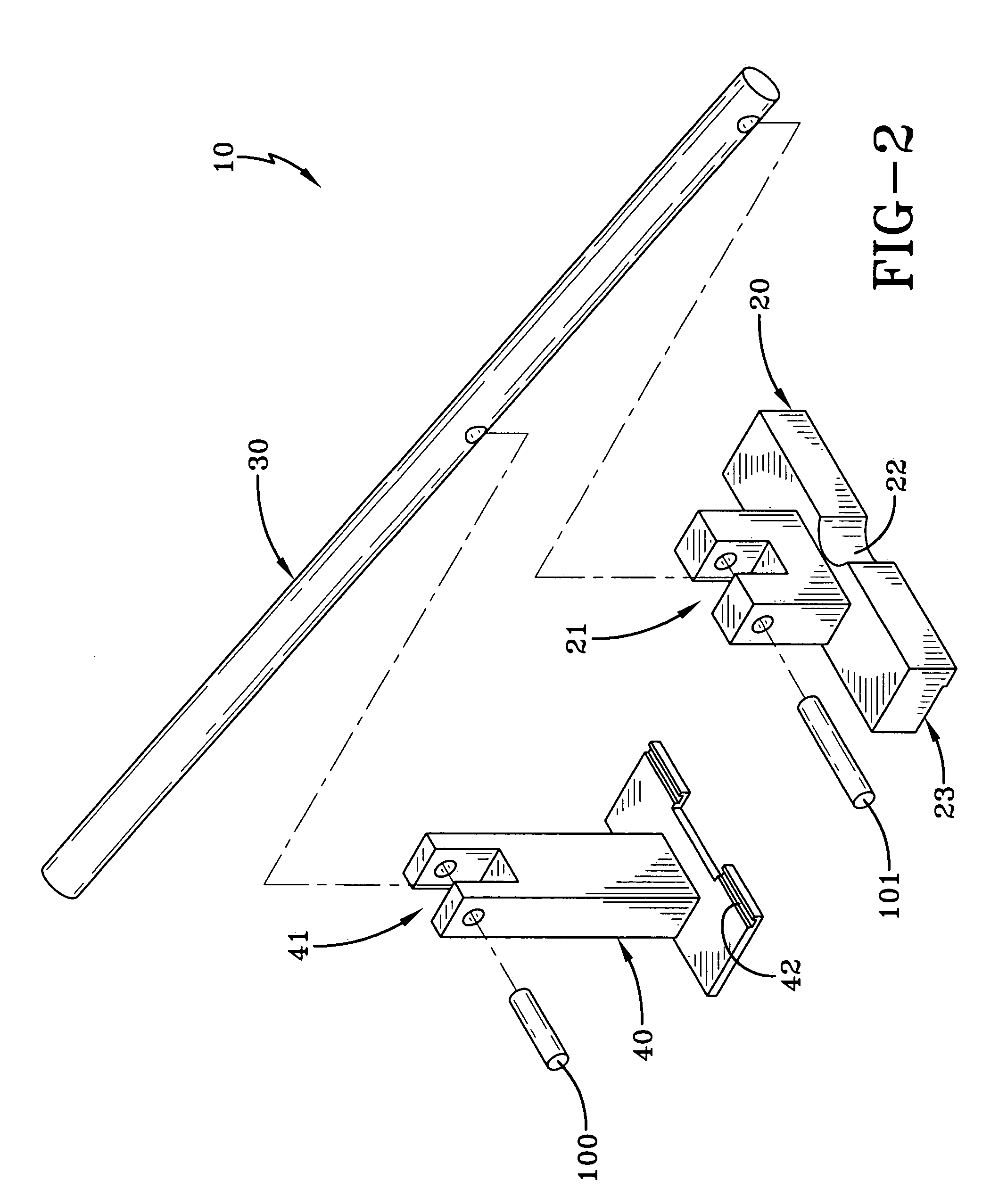
[0018]One embodiment of the engine cover puller of the present invention can be seen by reference to FIGS. 1 and 2. As can be observed, the engine cover puller 10 is comprised of a base 20, a lever arm 30, and a puller arm 40. The base 20 and puller arm 40 are shown pivotably connected to the lever arm 30 at 21 and 41, respectively. A pivot pin 100 is shown at the pivotable connection 41 between the puller arm 40 and the lever arm 30. Also shown is a pivot pin 101 at the pivotable connection 21 between the base 20 and the lever arm 30. In this manner, the pivotable connections at 21 and 41 allow for placement of the base 20 and the engagement of the puller arm 40 to achieve and maintain an alignment with a cover to be removed during a substantial portion of movement of the lever arm 30 to effect the separation of an engine cover from a sealing surface with an engine. In other words, the lever arm 30 is pivotably mounted to the base 20 at 21 so that the lever arm 30 may pivot about ...


PUM

PropertyMeasurementUnit
Forceaaaaaaaaaa
Deformation enthalpyaaaaaaaaaa

Abstract

A device for facilitating the separation and removal of an engine cover from a sealing surface on an engine. The engine cover puller may reduce or eliminate the deformation of an engine cover during its removal and allows for its potential reuse. In addition, the engine cover puller may reduce or eliminate the damage to the sealing surfaces between the engine cover and the engine that may occur during an engine cover removal.

Description

BACKGROUND AND SUMMARY OF THE INVENTION[0001]The present invention relates to a device for facilitating the separation and removal of an engine cover from a sealing surface on an engine. The present invention may reduce or eliminate the deformation of an engine cover during its removal and allows for its potential reuse. In addition, the present invention may reduce or eliminate the damage to the sealing surfaces between the engine cover and the engine that may occur during an engine cover removal.[0002]A typical engine cover removal, such as the removal of a valve cover from a cylinder body, usually requires breaking a seal between the cover and the engine. This task, absent the use of the present invention, typically involves the mechanic inserting an item, such as a flat blade screwdriver, between the cover and the engine. Once the screwdriver is inserted, the mechanic pries the cover from the sealing surface on the engine. This can result in damage to the sealing surfaces betwee...

Claims


Application Information

Patent Timeline
IPC IPC(8): B23P19/00B25F1/00
CPCB25B27/0035B25B33/00Y10T29/53909Y10T29/49815Y10T29/49822Y10T29/53983Y10T29/53896Y10T29/49721
Inventor WYRICK, BARRY LYNNOVERMAN, BILLY WAYNEMOORE, BRUCE
Owner HONDA MOTOR CO LTD
Why Eureka
Try Eureka