Fine-adjustment mechanism to preset a miter saw for precision miter cuts

a technology of fine adjustment and miter saw, which is applied in the field of fine adjustment mechanism of preset miter saw for precision miter cuts, can solve the problems of inability to use with smaller table saws or miter saws, inability to use table saws with other than rectangular tops, and inability to fine adjustment. fine adjustment and other issues to achieve the effect of economic and efficien

Inactive Publication Date: 2006-10-03
CREDO TECH CORP
View PDF27 Cites 34 Cited by
  • Summary
  • Abstract
  • Description
  • Claims
  • Application Information

AI Technical Summary

Benefits of technology

[0016]The present invention satisfies the need for an economical and efficient fine-adjustment system for use with a variety of saws, including a miter saw. The present invention provides a fine-adjustment mechanism that is attached to a lever such that the lever and the cutting tool can finely adjust the angle of cut.

Problems solved by technology

Due to the interaction between the lever and the detent, however, the prior art arrangements do not allow for a fine adjustment that is near one of the predetermined detent positions.
Furthermore, a bulky microadjuster located on top of the track of the table saw makes it difficult to use with smaller table saws or miter saws.
One drawback of this type of prior art is its inability for use with table saws that have other than rectangular tops.
It would be impossible to use this application on cutting tools having a circular base, such as miter saws.
They do not, however, provide a mechanism for finely adjusting the angle of cut, such that the angle can be adjusted plus or minus a few degrees of the selected position.
First, no prior art provides a fine-adjustment mechanism for use with a cutting tool having a circular base, such as a miter saw.
Those disclosing the use of a lever to position a cut fail to provide a mechanism for microadjustments.
Furthermore, it is difficult to finely adjust the lever as the lever normally engages a recess in a worktable.
As the lever moves within a few degrees of the recess in a worktable, the lever naturally propagates into the recess making it very difficult for microadjustments.
Second, the prior art does not provide for an easy method of making a fine adjustment as most fine adjustments are bulky or must be clamped into position.
Finally, the prior art microadjustment mechanisms, because of the number of parts needed to create the device, are not economically viable.

Method used


Image

  • Fine-adjustment mechanism to preset a miter saw for precision miter cuts
  • Fine-adjustment mechanism to preset a miter saw for precision miter cuts
  • Fine-adjustment mechanism to preset a miter saw for precision miter cuts

Examples


Embodiment Construction

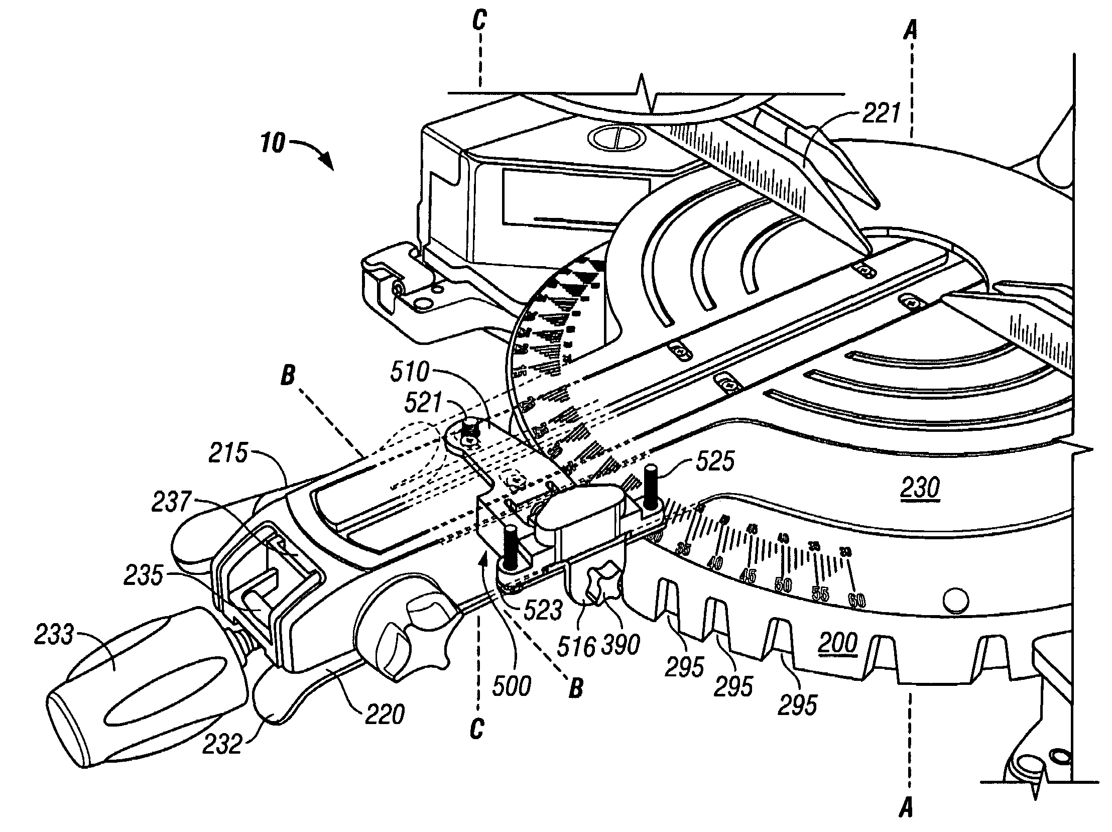
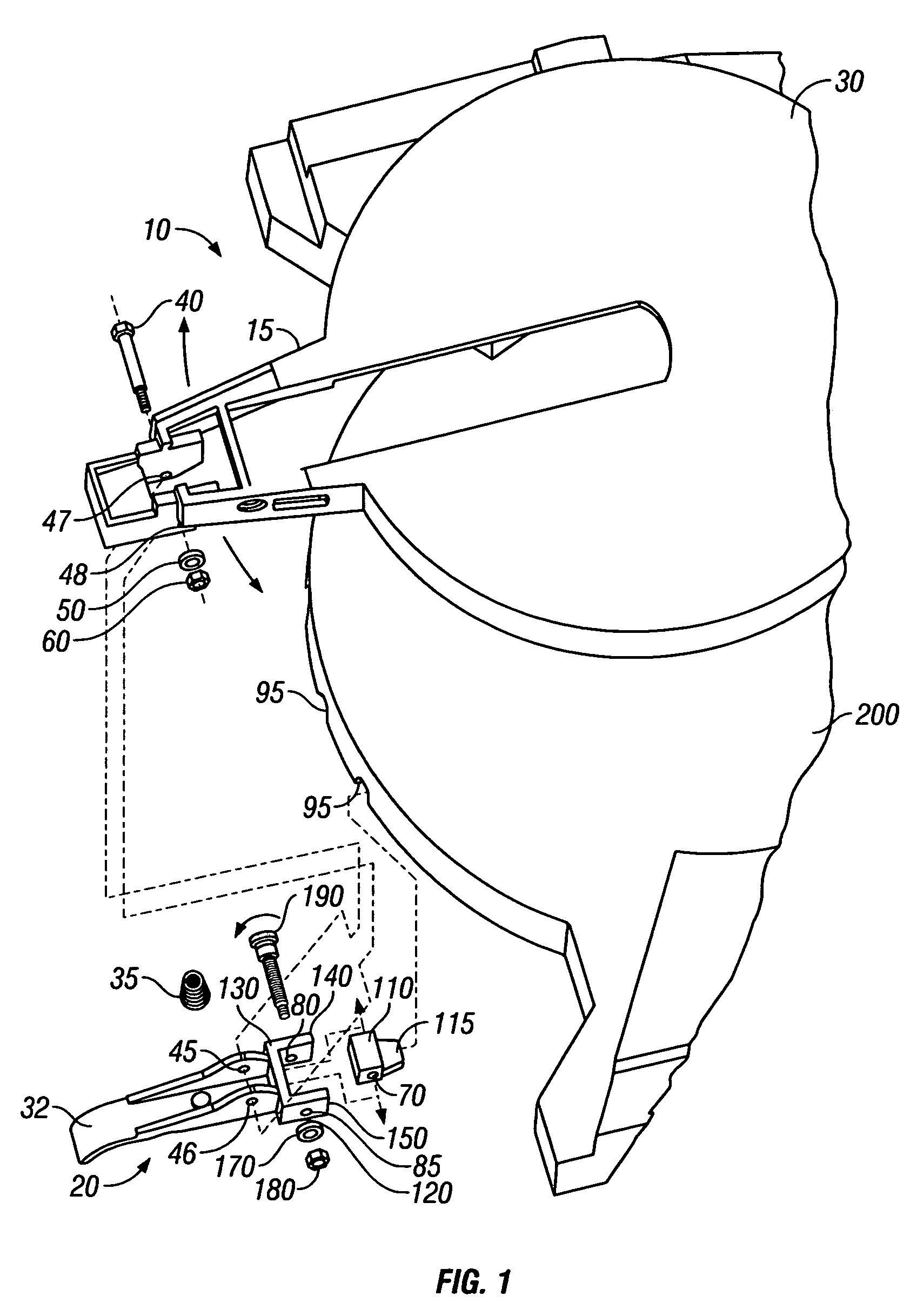
[0042]Turning first to FIG. 1, there is illustrated, in accordance with a first embodiment of the present invention, a miter saw assembly 10. The miter saw assembly 10 includes a stationary base 200 and a turntable 30 that is rotatably mounted to the base 200. A cutting tool (e.g., power saw) is mounted to the turntable 30 so that rotation of the turntable 30 with respect to the base 200 in turn moves the cutting tool to a desired miter angle. The rotatable turntable 30 has a forwardly extending arm portion 15 to which a movable lever 20 is secured. The lever 20 is operable to selectively engage one of several recesses 95 in the base 200 to lock the turntable 30 relative to the base 200 at a selected angle of cut. In an embodiment, each of the recesses 95 is positioned to correspond to a particular angle for a common miter, e.g., 0°, 15°, 30°, 45°, etc.

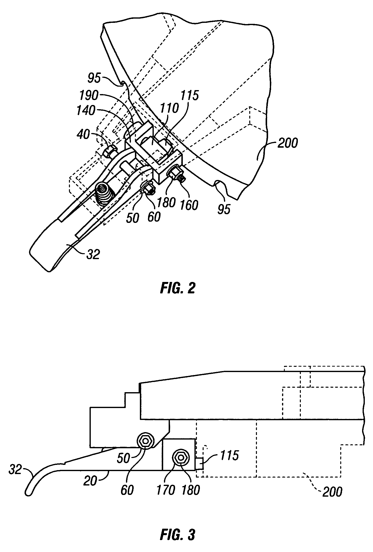
[0043]FIGS. 1–5 illustrate a lever 20 including an elongate lever body portion and a yoke portion 120 at an end of the lever body. A...


PUM

PropertyMeasurementUnit
angleaaaaaaaaaa
angleaaaaaaaaaa
angleaaaaaaaaaa

Abstract

A fine-adjustment mechanism for making small adjustments to a cutting angle on a miter saw. The mechanism is used in conjunction with an apparatus that includes a base having at least one recess, and a turntable that supports a cutting tool is rotatably mounted to the base. An angular-adjustment lever is pivotally mounted to the turntable. The angular-adjustment lever includes a first insert proximal to the turntable. The first insert is capable of engaging at least one recess. The fine-adjustment mechanism is mounted to the turntable and includes a fine-adjustment lever pivotally mounted on the turntable. The fine-adjustment lever may include a plurality of notches. A second insert having an opening therethrough is supported by the fine-adjustment lever and adapted to engage at least one recess of the base. A threaded rod supported by the fine-adjustment lever extends through the opening in the second insert. A latch holder may be attached to the fine-adjustment lever. The latch holder contains a spring secured by a retainer plate and a latch having a plurality of protrusions capable of mating with the plurality of notches in the fine-adjustment lever.

Description

CROSS-REFERENCE TO RELATED PATENT APPLICATIONS[0001]This patent application is a continuation-in-part of U.S. patent application Ser. No. 10 / 135,299 filed Apr. 30, 2002 now abandoned.FIELD OF THE INVENTION[0002]This invention pertains to power tools and, more particularly, to a miter cut adjustment mechanism for use with a cutting tool that allows for adjustment of a cutting angle to a number of predetermined positions as well as precise adjustment of the angle near the predetermined positions.BACKGROUND OF THE INVENTION[0003]A miter saw typically has the capacity to crosscut work pieces placed against its horizontal table and vertical fence. This saw can be rotated to make vertical cuts through a work piece at various angles relative to the fence. A vertical cut is known as a “miter cut.”[0004]A compound miter saw has the capability to tilt the blade (counterclockwise) to an angle relative to the table, generally from 0° to 45° left of vertical. A cut made with the blade tilted at ...

Claims


Application Information

Patent Timeline
Patent Type & Authority Patents(United States)
IPC IPC(8): B23D19/00B27B5/00B23D45/04B23D47/02B27B5/29
CPCB23D47/025B27B5/29Y10T83/6975Y10T83/7697Y10T83/7788Y10T83/8773
Inventor ROMO, EZEQUIELSVETLIK, KENNETH N.
Owner CREDO TECH CORP
Why Eureka
Try Eureka