Coupling structure for grinding members

a technology of coupling structure and grinding member, which is applied in the direction of grinding machine components, manufacturing tools, grinding machines, etc., can solve the problems of extra cost, and achieve the effect of improving the coupling structure and reducing the cos

Inactive Publication Date: 2006-10-03
SUNMATCH INDAL
View PDF5 Cites 33 Cited by
  • Summary
  • Abstract
  • Description
  • Claims
  • Application Information

AI Technical Summary

Benefits of technology

[0004]Therefore the primary object of the present invention is to provide an improved coupling structure for grinding members that adopts a removable design so that one or more grinding member can be coupled or replaced. And the coupling structure can be used repeatedly. Thus the cost may be reduced.

Problems solved by technology

This results in an extra cost.

Method used


Image

  • Coupling structure for grinding members
  • Coupling structure for grinding members
  • Coupling structure for grinding members

Examples


Embodiment Construction

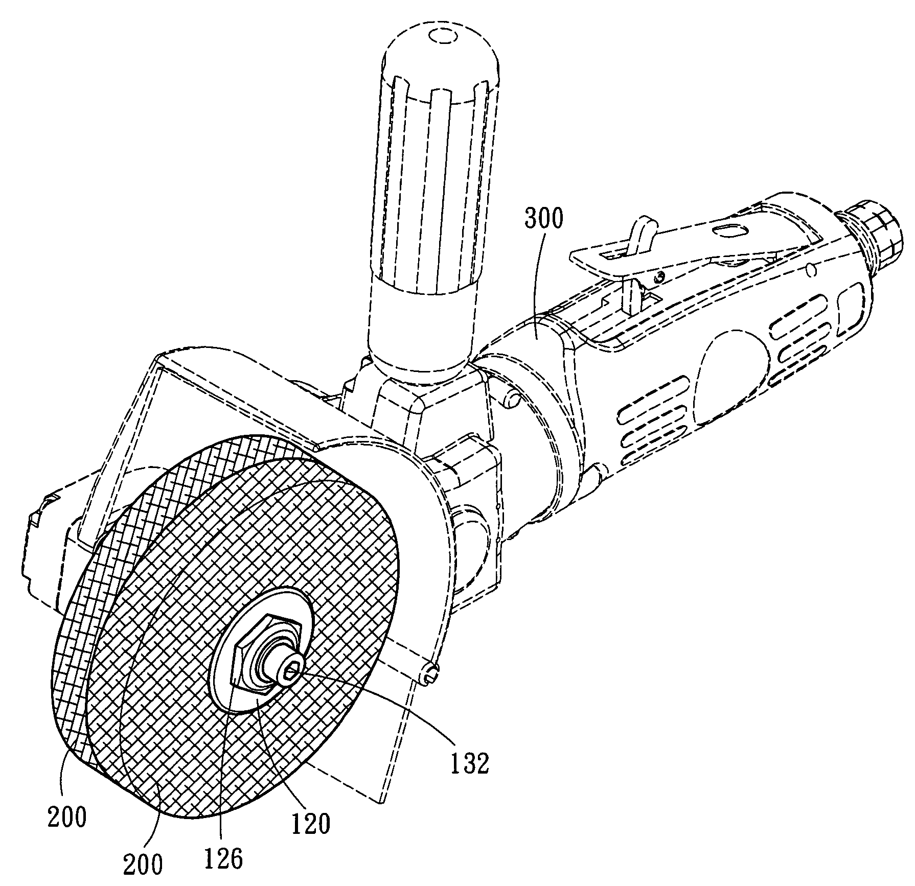
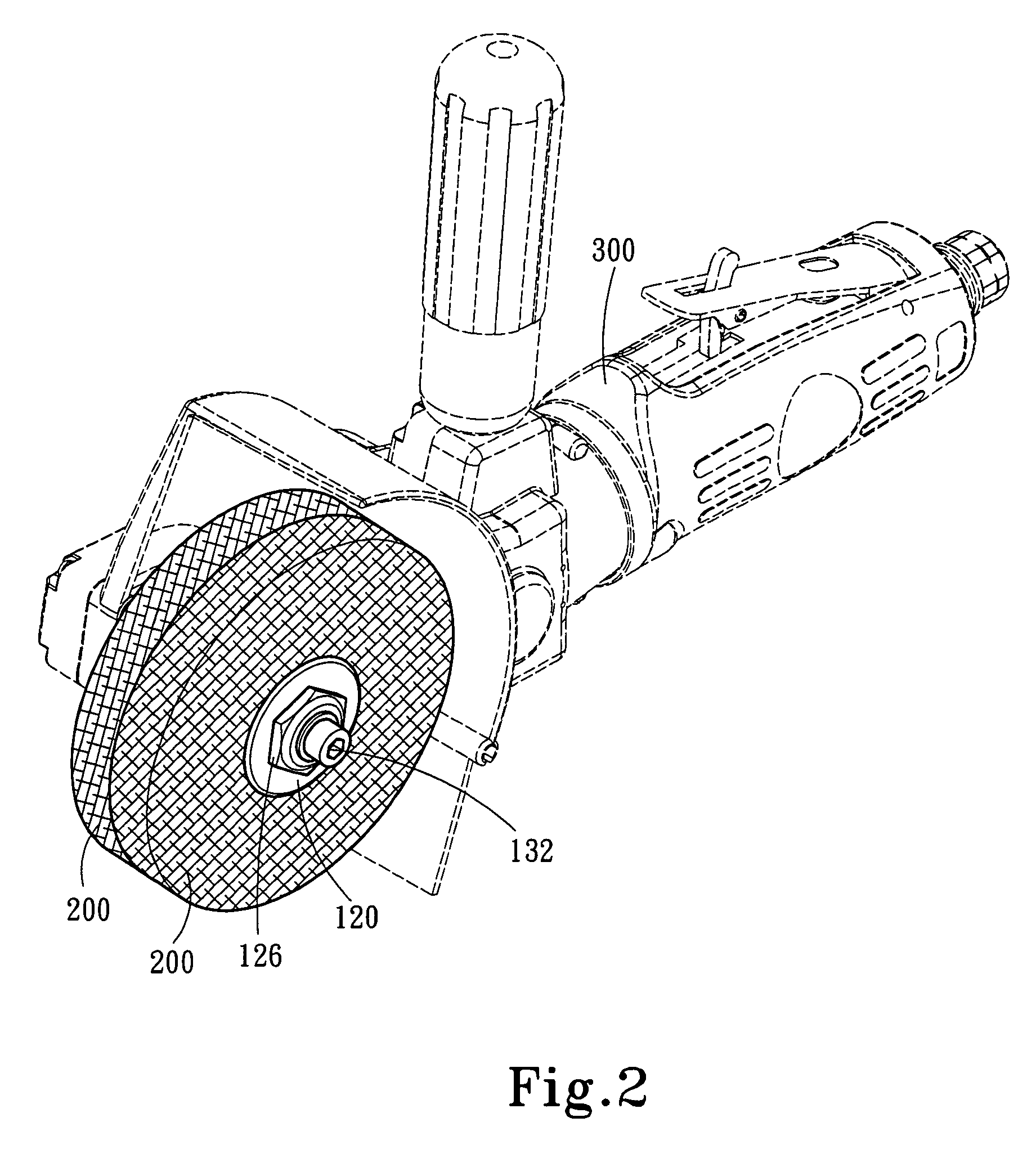
[0012]Please referring to FIGS. 2, 3 and 4, the coupling structure for grinding members according to the invention aims to couple at least one grinding member 200 to a pneumatic tool 300. In an embodiment of the invention, the coupling structure mainly includes a first clamping disk 110, a second clamping disk 120 and a fastening element 130.

[0013]The first clamping disk 110 has a sleeve 112 extended from the center of one side. The sleeve 112 has a first aperture 114 running through the first clamping disk 110. The sleeve 112 can run through an opening 202 formed in the center of the grinding member 200. The second clamping disk 120 has a second aperture 122 in the center. The sleeve 112 runs through the grinding member 200 and the second aperture 122 of the second clamping disk 120. The fastening element 130 can run through the first aperture 114 and the second aperture 122 to hold the grinding member 200 between the first clamping disk 110 and the second clamping disk 120, thereb...


PUM


Abstract

A coupling structure for grinding members adopts a removable structure to fasten a grinding member to a pneumatic tool. One or more grinding member may be mounted on the coupling structure according to requirements. The coupling structure may be used repeatedly to reduce costs.

Description

FIELD OF THE INVENTION[0001]The present invention relates to an improved coupling structure for grinding members and particularly to a removable coupling structure adopted for use on pneumatic tools.BACKGROUND OF THE INVENTION[0002]The common pneumatic tool aims to provide a driving force through a pneumatic motor to rotate a spindle and drive a grinding member coupled on a distal end of the spindle to perform grinding operation. Refer to FIG. 1 for a conventional grinding member 10 which is coupled with a fastening element 11 in an integrated manner. The fastening element 11 has a screw thread 12 on a distal end to be fastened to a coupling head 22 of a pneumatic tool 20.[0003]As the grinding member 10 and the fastening element 11 are fabricated in an integrated manner, when the grinding member 10 has been used for a period of time and has to be replaced, the fastening element 11 also is discarded. This results in an extra cost. Moreover, with the grinding member 10 and the fasteni...

Claims


Application Information

Patent Timeline
Patent Type & Authority Patents(United States)
IPC IPC(8): B24B23/00
CPCB24D5/16
Inventor CHEN, LUNG-PAO
Owner SUNMATCH INDAL
Why Eureka
Try Eureka