Vehicular lamp

a technology of vehicle lamps and lampshades, which is applied in the direction of lighting and heating apparatus, instruments, lighting support devices, etc., can solve the problems of shortening the life of semiconductor light emitting devices, and achieve the effect of reducing the electric curren

Inactive Publication Date: 2006-10-03
KOITO MFG CO LTD
View PDF12 Cites 21 Cited by
  • Summary
  • Abstract
  • Description
  • Claims
  • Application Information

AI Technical Summary

Benefits of technology

[0009]The electric current supplying unit may decrease the electric current to be supplied to the plurality of semiconductor light emitting devices from the second electric current to a third electric current, which is lower than the second electric current, when the wire breakage detecting unit detects wire breakage of at least two of the plurality of semiconductor light emitting devices.
[0010]The vehicular lamp may further include: a plurality of electric current detecting units provided corresponding to the plurality of semiconductor light emitting devices, each of the plurality of electric current detecting units detecting electric current flowing through corresponding one of the plurality of semiconductor light emitting devices; and an average electric current value output unit selecting at least one of the plurality of electric current detecting units corresponding to respective one(s) of the plurality of semiconductor light emitting devices of which the wire breakage is not detected by the corresponding wire breakage detecting unit, and outputting an average value of electric current detected by the selected electric current detecting unit. The electric current supplying unit may decreases the electric current to be supplied to the plurality of semiconductor light emitting devices so that the average value may be maintained substantially constant when at least one of the wire breakage detecting units detects wire breakage of respective one(s) of the semiconductor light emitting devices.

Problems solved by technology

However, if the excessive electric current flows in the semiconductor light emitting device, the life of the semiconductor light emitting device may become shorter due to heat generation.

Method used


Image

  • Vehicular lamp
  • Vehicular lamp
  • Vehicular lamp

Examples


Embodiment Construction

[0017]The invention will now be described based on the preferred embodiments, which do not intend to limit the scope of the present invention, but exemplify the invention. All of the features and the combinations thereof described in the embodiment are not necessarily essential to the invention.

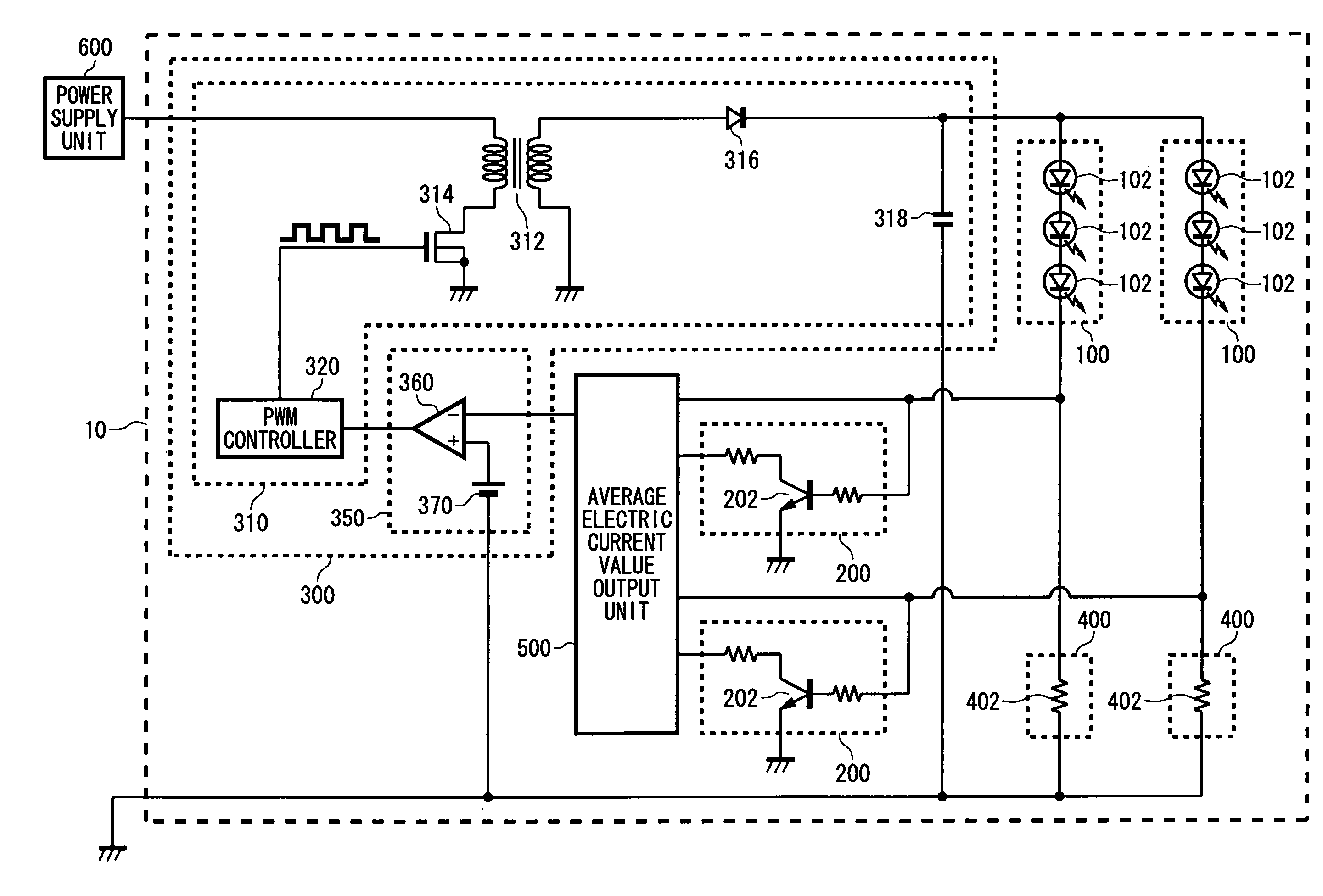
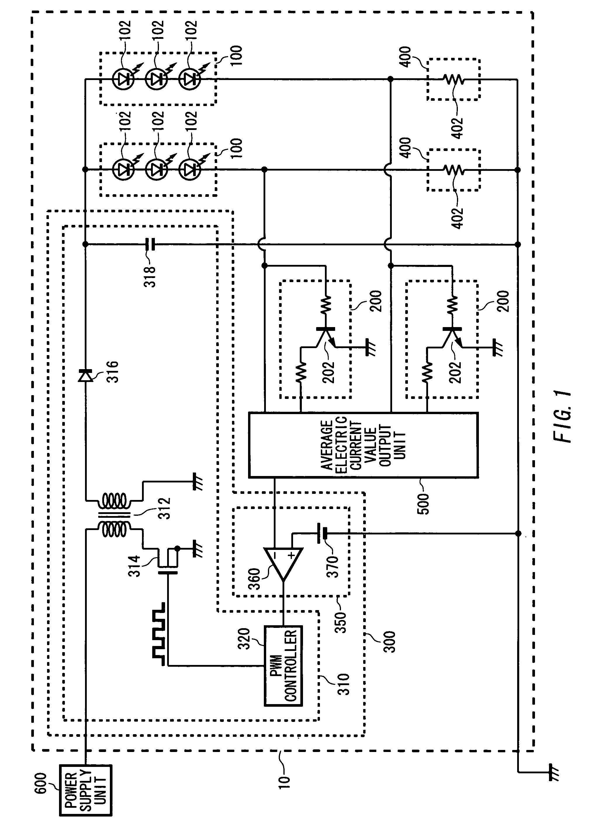
[0018]FIG. 1 is a circuit diagram illustrating a configuration of a vehicular lamp 10 and a power supply unit 600 according to an embodiment of the present invention. In the present embodiment, the vehicular lamp 10 is configured for supplying electric current appropriately to semiconductor light emitting devices 102 included in the vehicular lamp 10. The power supply unit 600 supplies electric power to the vehicular lamp 10. The electric power may be dependent on the power of a battery loaded on a vehicle.

[0019]For example, the vehicular lamp 10 is a headlamp of vehicle for lighting road ahead of the vehicle. Alternatively, the vehicular lamp 10 is, but not limited to, a stop lamp, a tail la...


PUM


Abstract

Electric current supplied to light source rows of a vehicular lamp is controlled appropriately. The vehicular lamp includes: a plurality of semiconductor light emitting devices connected in parallel; a wire breakage detecting unit detecting wire breakage of each of the plurality of semiconductor light emitting devices; and an electric current supplying unit supplying a predetermined electric current to the plurality of semiconductor light emitting devices. The electric current supplying unit decreases the electric current to be supplied to the plurality of semiconductor light emitting devices when the wire breakage detecting unit detects wire breakage of at least one of the plurality of semiconductor light emitting devices.

Description

[0001]The present application claims priority from a Japanese Patent Application No. 2003-124430 filed on Apr. 28, 2003, the contents of which are incorporated herein by reference.BACKGROUND OF THE INVENTION[0002]1. Field of the Invention[0003]The present invention relates to a vehicular lamp. More particularly, the present invention relates to a headlamp, a stop lamp, a tail lamp, a turn lamp, and the like used for a vehicle including automobiles, motorcycles and trains.[0004]2. Related Art[0005]A vehicular lamp employing a semiconductor light emitting device is known (e.g., Japanese Patent Laid-Open No. 2002-231014 bulletin (page 3–6, FIG. 1–13)). In general, the vehicular lamp has to be on stably for safety reasons.[0006]However, if the excessive electric current flows in the semiconductor light emitting device, the life of the semiconductor light emitting device may become shorter due to heat generation. Therefore, for the vehicular lamp using a semiconductor light emitting devi...

Claims


Application Information

Patent Timeline
Patent Type & Authority Patents(United States)
IPC IPC(8): B60Q1/14B60Q11/00F21V21/00H05B41/36B60Q1/00B60Q1/04B60Q1/34B60Q1/44H05B44/00
CPCB60Q11/00H05B33/0815H05B33/0827H05B33/0887H05B45/50H05B45/46H05B45/382
Inventor ITO, MASAYASUTAKEDA, HITOSHI
Owner KOITO MFG CO LTD
Why Eureka
Try Eureka