Method and apparatus for controlled persistent ID flag for RFID applications

a technology of rfid tags and id flags, applied in the field of radio frequency identification (rfid) transponders, can solve the problems of mainly leakage, inefficient process of identifying a rfid tag that has previously been identified, and loss of state information of rfid tags that are not well powered

Active Publication Date: 2006-10-03
IMPINJ
View PDF14 Cites 64 Cited by
  • Summary
  • Abstract
  • Description
  • Claims
  • Application Information

AI Technical Summary

Problems solved by technology

The RFID tags that are not well powered lose track of state information.
This process of again identifying an RFID tag that has previously been identified is, of course, inefficient.
Of course, leakage may be primarily due to switches connected to the capacitor and not through the capacitor itself.
Because the leakage current may vary with temperature, an RFID tag with a certain size capacitor may not retain state information as long as necessary at high temperatures and retain state information longer than is practicable at low temperatures.

Method used


Image

  • Method and apparatus for controlled persistent ID flag for RFID applications
  • Method and apparatus for controlled persistent ID flag for RFID applications
  • Method and apparatus for controlled persistent ID flag for RFID applications

Examples


Embodiment Construction

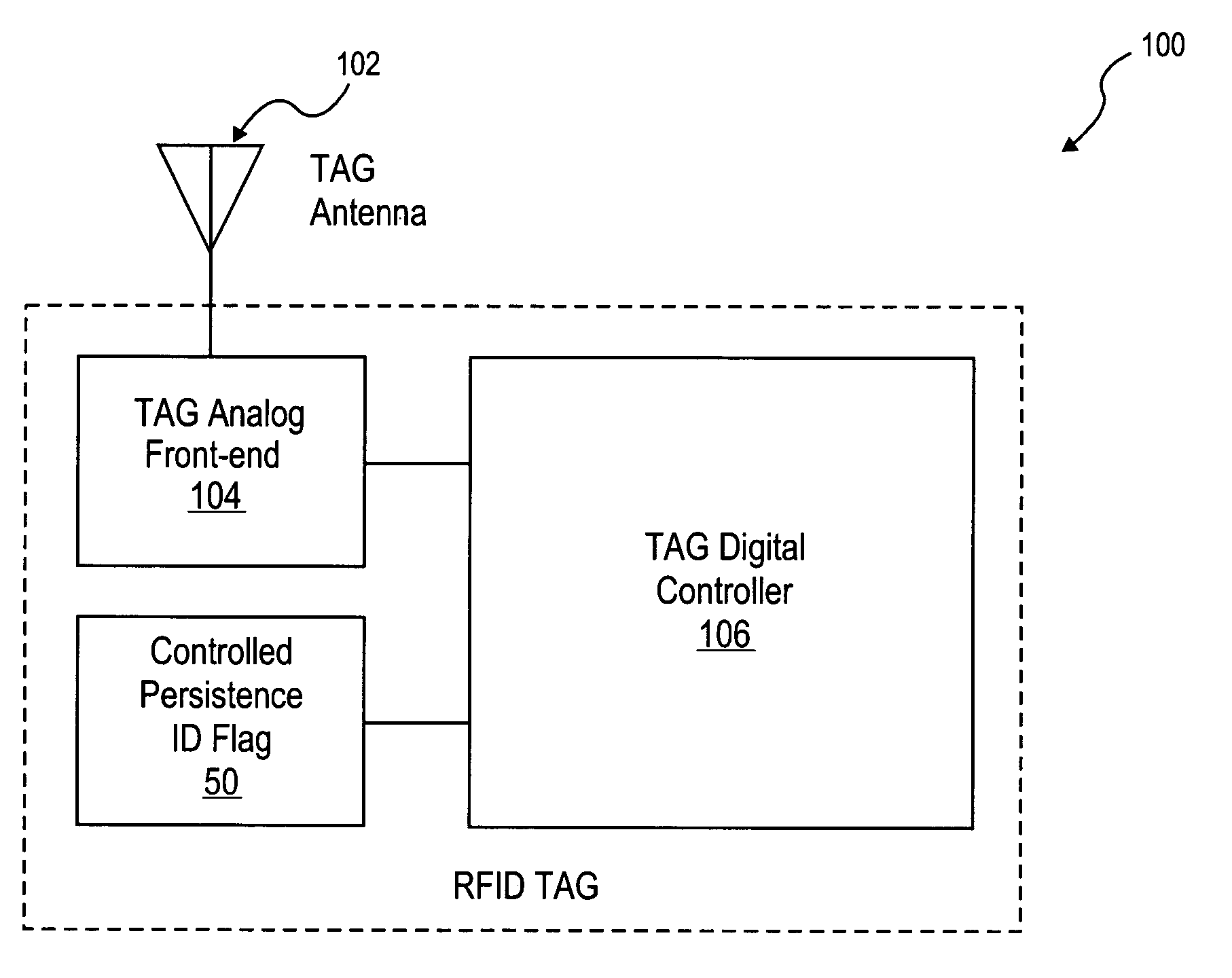
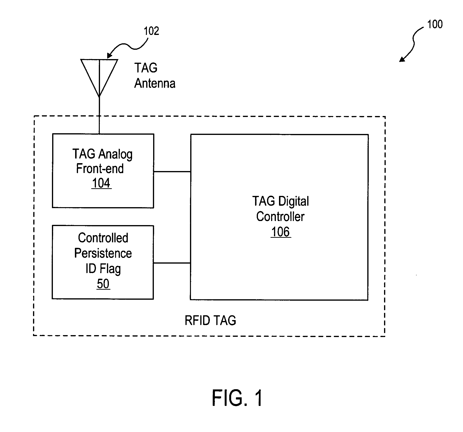
[0031]A method and apparatus to implement a controlled persistent identification (ID) flag for RFID applications are described. In the following description, for purposes of explanation, numerous specific details are set forth in order to provide a thorough understanding of the present invention. It will be evident, however, to one skilled in the art that the present invention may be practiced without these specific details.

[0032]Because passive RFID tags do not have an independent source of power, it may be desirable that the tag state can be maintained during the temporary power loss (e.g., when the RFID tag is no longer illuminated by an interrogator RF signal). Passive RFID tags receive power from an RF link. An RF link may not be reliable and thus temporary power drops are not uncommon. The following scenario may illustrate a situation that an ID flag or persistent storage bit is intended to address.

[0033]Consider a population of tags, for example, affixed to a number of cases ...


PUM


Abstract

A Radio-Frequency Identification (RFID) transponder is provided. The RFID transponder may include a basic ID flag circuit having a VDD voltage node, an output voltage node, and a capacitor coupled to the VDD voltage node and the output voltage node to store an ID flag. The persistence duration of the state of the ID flag is controlled by maintaining a charge and leakage circuit. The charge and leakage circuit includes an NMOS device having a source, a drain and a gate, the source node of the NMOS device being coupled to the capacitor and the drain node of the NMOS device being coupled to a first CMOS inverter. The first CMOS inverter is powered by a regulated supply voltage such that the voltage on the capacitor is not dependent on the forward voltage drop of the NMOS device.

Description

RELATED APPLICATIONS[0001]The present application is a continuation of incorporates by reference and hereby claims the priority benefit of the following U.S. patent application, assigned to the assignee of the present application:[0002]U.S. patent application Ser. No. 10 / 887,617, filed Jul. 8, 2004, entitled “Method and Apparatus for Controlled Persistent ID Flag for RFID Applications,”[0003]which is related to, incorporates by reference and hereby claims the priority benefit of the following U.S. Provisional Patent Application:[0004]U.S. Provisional Patent Application No. 60 / 562,154, filed Apr. 13, 2004, entitled “Method and Apparatus for Controlled Persistent ID Flag for RFID Applications.”FIELD OF THE INVENTION[0005]One exemplary embodiment relates generally to the field of Radio Frequency Identification (RFID) transponders (e.g., RFID tags) and more specifically to a method and apparatus for controlled persistent ID flag for RFID applications.BACKGROUND OF THE INVENTION[0006]Rad...

Claims


Application Information

Patent Timeline
Patent Type & Authority Patents(United States)
IPC IPC(8): G08B21/00G06K19/07G11C5/00H04Q5/22
CPCG06K19/0723
Inventor HYDE, JOHN D.
Owner IMPINJ
Why Eureka
Try Eureka