Method for determining signal quality in optical transmission systems

a technology of optical transmission system and signal quality, applied in the direction of transmission monitoring, multiplex communication, instruments, etc., can solve the problem of no longer being able to ascertain a violation of code rules

Inactive Publication Date: 2006-10-03
XIEON NETWORKS SARL
View PDF9 Cites 12 Cited by
  • Summary
  • Abstract
  • Description
  • Claims
  • Application Information

AI Technical Summary

Benefits of technology

[0012]Mathematical transformations, in particular, enable a simple comparison between measured histogram values and calculated or measured comparison values, since a histogram moments term containing average values and variances of the sampling amplitude distributions of the binary states is linearly dependent on the signal-to-noise ratio.

Problems solved by technology

However, in the required monitoring of the signal quality, it is then no longer possible to ascertain a violation of code rules; for example, in the case of error correcting codes.

Method used


Image

  • Method for determining signal quality in optical transmission systems
  • Method for determining signal quality in optical transmission systems
  • Method for determining signal quality in optical transmission systems

Examples


Embodiment Construction

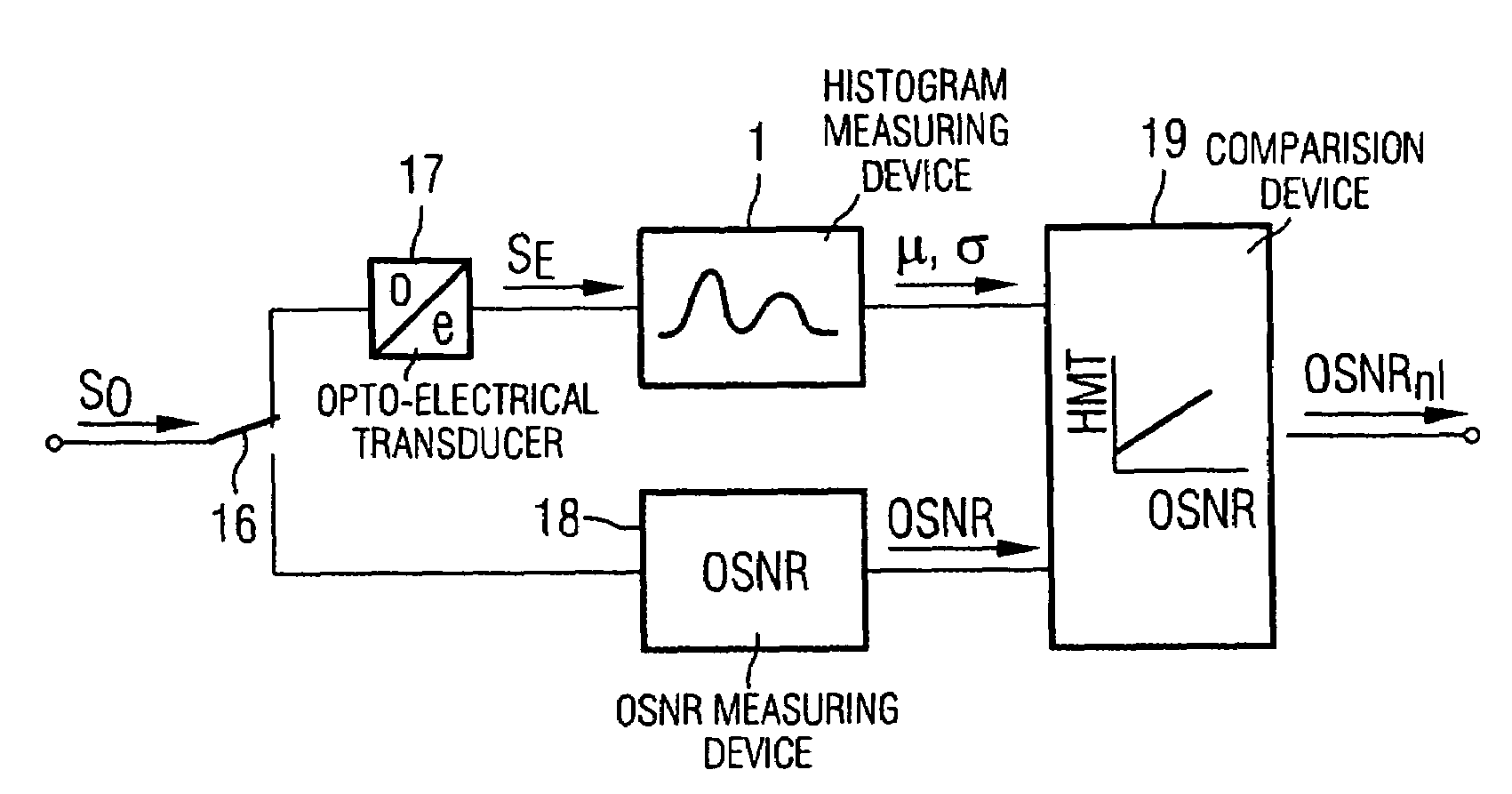
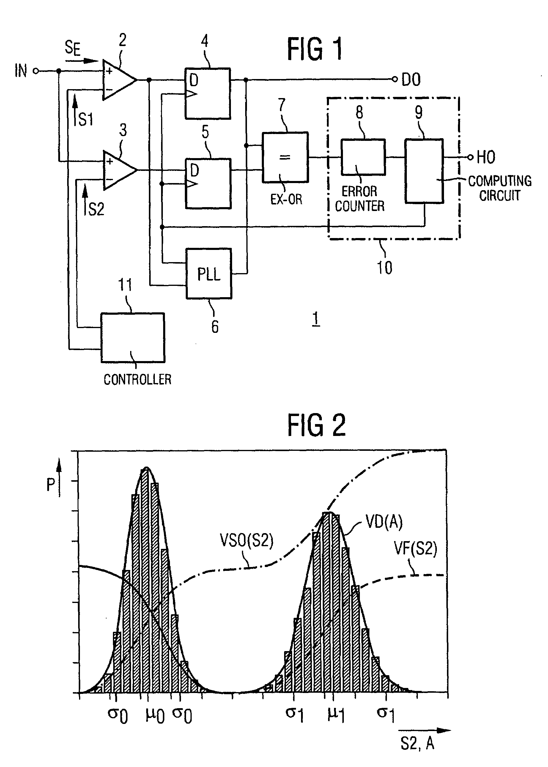
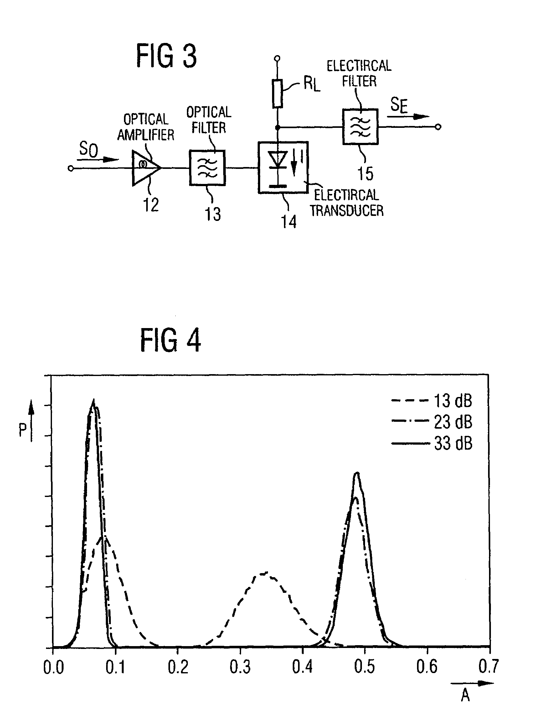
[0020]The known measuring device 1 for amplitude histograms which is illustrated in FIG. 1 serves for determining the probability density distribution of samples through measurements at different sampling thresholds.

[0021]The measuring device 1 contains two decision stages 2 and 3, to whose first inputs an already converted electrical signal SE is fed via a data signal input IN, the signal having been transmitted beforehand as an optical signal via a link section or the entire transmission link. The decision threshold of at least one of the decision stages 2 and 3 is adjustable via a controller 11; here through the application of comparison voltages corresponding to threshold values S1 and S2.

[0022]The outputs of the decision stages are respectively connected to a sampling flip-flop 4 and 5, whose data outputs are fed to an Exclusive-OR gate 7. The output of this gate is connected to an error counter 8 which, like a computing circuit 9, is part of a histogram computer 10.

[0023]Moreo...


PUM


Abstract

A method for determining signal quality in optical transmission systems, wherein the effective signal-to-noise ratio is determined by measuring amplitude histograms of a signal and by calculating characteristic histogram moments and additional interference is ascertained by comparing the characteristic histogram moments with the optical signal-to-noise ratio.

Description

BACKGROUND OF THE INVENTION[0001]The present invention relates to a method for determining the signal quality in optical transmission systems and for determining interfering effects.[0002]In the future, transmission networks will be embodied as optical networks via which data will be transmitted at extremely high bit rates using the wavelength division multiplex method. In this context, extensive transparency of the networks is sought. However, in the required monitoring of the signal quality, it is then no longer possible to ascertain a violation of code rules; for example, in the case of error correcting codes. Therefore, methods are being developed which enable the signal quality to be assessed independently thereof.[0003]In a method described in published patent application DE 195 04 856, amplitude samples are taken asynchronously with respect to the signal clock and the central moments of the sample are calculated therefrom. These are then compared with empirically obtained ref...

Claims


Application Information

Patent Timeline
Patent Type & Authority Patents(United States)
IPC IPC(8): H04B10/08H04B17/00H04B10/00H04B10/02H04B10/079
CPCH04B10/07953
Inventor ELBERS, JOERG PETERGLINGENER, CHRISTOPHFAERBERT, ANDREASSCHEERER, CHRISTIAN
Owner XIEON NETWORKS SARL
Why Eureka
Try Eureka