Practical, redundant, failure-tolerant, self-reconfiguring embedded system architecture

Inactive Publication Date: 2006-10-03
NAT TECH & ENG SOLUTIONS OF SANDIA LLC
31 Cites 38 Cited by

AI-Extracted Technical Summary

Problems solved by technology

This system could be used in any distributed computing system that requires multiple levels ...

Benefits of technology

[0010]The invention supports failure-tolerant hardware configuration, has simple implementation requirements, allows for heterogeneous hardware platforms, and has ...

Abstract

This invention relates to system architectures, specifically failure-tolerant and self-reconfiguring embedded system architectures. The invention provides both a method and architecture for redundancy. There can be redundancy in both software and hardware for multiple levels of redundancy. The invention provides a self-reconfiguring architecture for activating redundant modules whenever other modules fail. The architecture comprises: a communication backbone connected to two or more processors and software modules running on each of the processors. Each software module runs on one processor and resides on one or more of the other processors to be available as a backup module in the event of failure. Each module and backup module reports its status over the communication backbone. If a primary module does not report, its backup module takes over its function. If the primary module becomes available again, the backup module returns to its backup status.

Application Domain

Technology Topic

Embedded systemSoftware modules +1

Image

  • Practical, redundant, failure-tolerant, self-reconfiguring embedded system architecture
  • Practical, redundant, failure-tolerant, self-reconfiguring embedded system architecture
  • Practical, redundant, failure-tolerant, self-reconfiguring embedded system architecture

Examples

  • Experimental program(1)

Example

Configuration of a Basic System
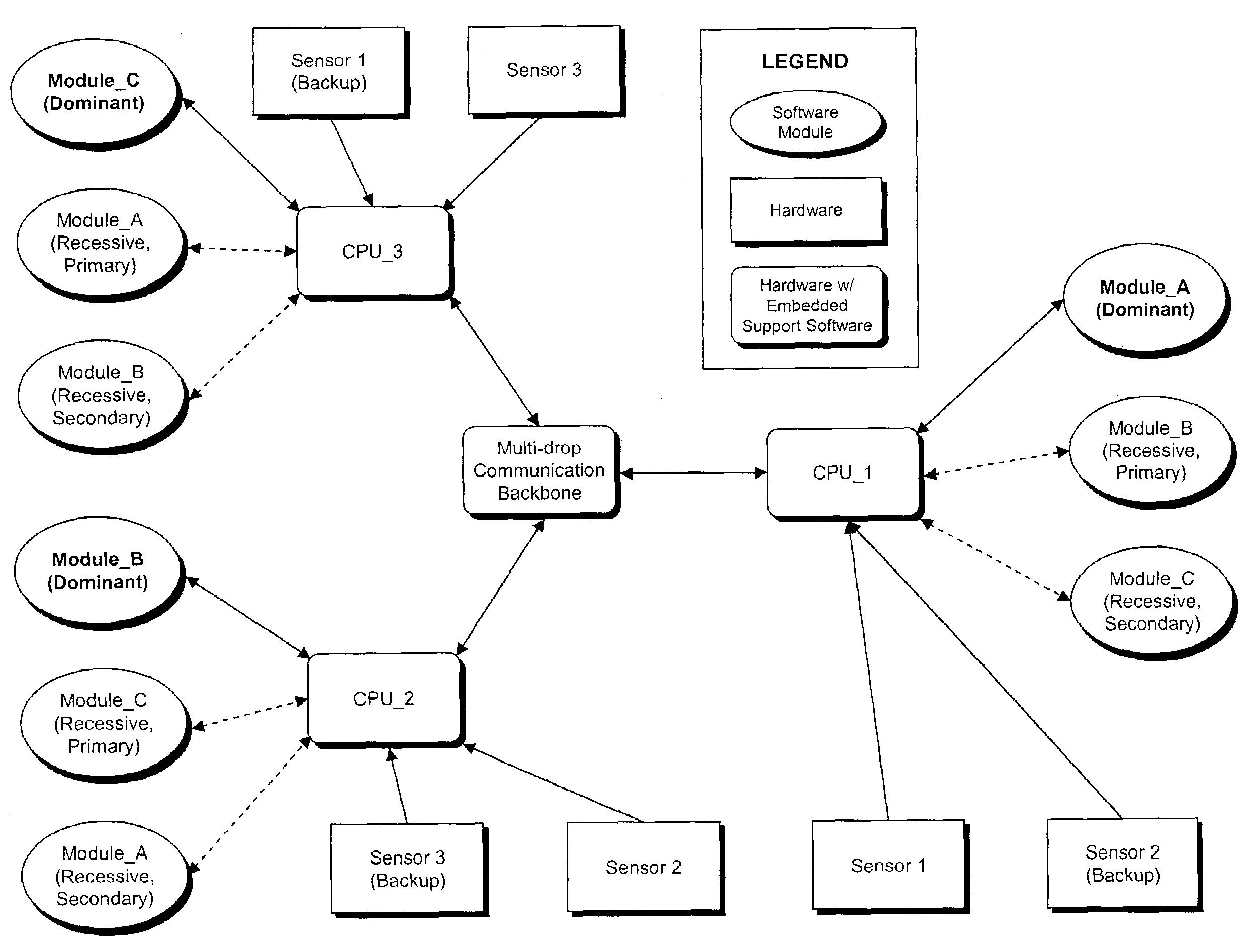
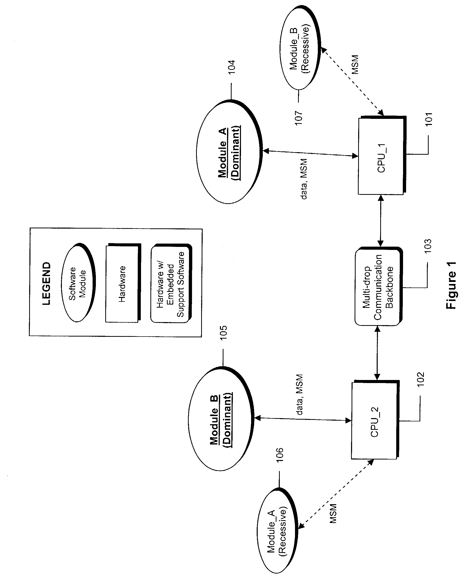
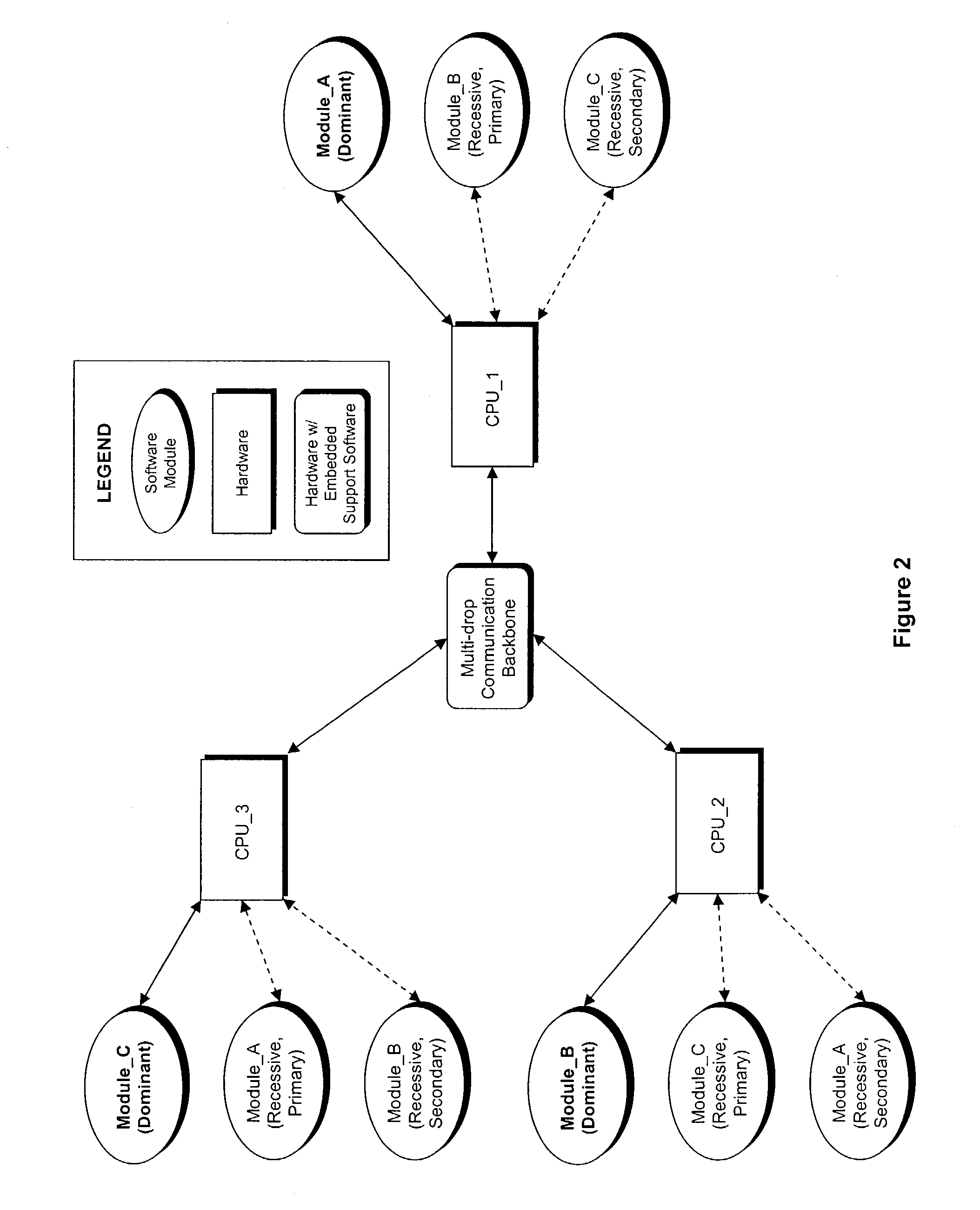
[0017]The system assumes a hardware architecture that supports distributed computing via a set of processors connected to a multi-drop communication backbone (i.e. Ethernet or RS485). Although a homogeneous set of processors is assumed, homogeneity is not a requirement and a heterogeneous set of processors can be accommodated. FIG. 1 illustrates a simple system configuration with all of the essential elements. The system consists of two processors, 101 and 102, connected to a communication backbone 103 and two software modules, 104 and 105. A copy of each software module, 106 and 107, resides on each processor, but one copy of each is designated as either ‘Dominant’ or ‘Recessive’ depending on which processor it resides on.
Operation of Software Module Redundancy
[0018]All modules monitor the communication backbone data traffic, looking for a circulating message containing a representation of the current functional state of all modules in the system, called the Module Status Message (MSM). The possible functional states for modules are ‘active’ or ‘inactive’. By default, ‘Dominant’ modules are ‘active’ and ‘Recessive’ modules are ‘inactive’. An ‘active’ module is receiving, processing, and outputting data as required for its intended functionality. It is also periodically updating the MSM with its functional condition, typically only noting that it is running. An ‘inactive’ module is not processing or outputting data, it is only monitoring the MSM and also periodically updating the MSM by noting its own functional condition. The implementation of such a system is well known to those of ordinary skill in the art.
[0019]When a failure occurs in either hardware or software, the MSM will reflect the functional loss of a module since that module is no longer updating the MSM appropriately. Using a watchdog monitoring scheme, the ‘Recessive’ (inactive) module can detect the loss of its associated ‘Dominant’ (active) module and will then activate itself to take over that functionality. If for some reason the lost ‘Dominant’ module becomes active again, the ‘Recessive’ module can detect that event in the MSM and will demote itself back to the inactive state. This inherent capability makes the system self-correcting for losses of either hardware or associated software functionality, and can revert to a previous configuration if the loss condition proves to be temporary. Implementation of the MSM itself can be as comprehensive as desired using a data blackboard structure shared (received, updated, and retransmitted) by all modules, or could be as simple as a bit-field containing single bit positions. Each bit corresponds to each software module in the system where a functional ‘active’ module simply toggles its bit at an appropriate update rate and ‘inactive’ modules monitor the toggle rate of appropriate bits to determine if the associated ‘Dominant’ module is running.
Module Implementation on CPUs
[0020]Each CPU can implement the control of its individual modules in a centralized or distributed fashion. In a centralized scheme, a main controller reviews the MSM and activates or deactivates modules on the CPU. In a distributed scheme, each module on a CPU independently reviews the MSM to determine whether it should become active or inactive. As such, a module is never really inactive, as some part of the module is still running in order to determine whether the module should become active. The activity state of a module is important for determining resource usage on a particular CPU. It is also important for deciding how context information is obtained by a ‘Recessive’ module when a switch occurs from the ‘Dominant’ module. Assuming each ‘Recessive’ module is running at some low level will allow each ‘Recessive’ module to maintain an up-to-date context so that it can be switched to with minimum of latency.
Multiple Levels of Redundancy
[0021]More complex configurations are supported by this architecture, as illustrated in FIG. 2. Multiple levels of redundancy are possible to virtually any level, limited only by processing capacity of individual processors and bandwidth limitations of the communication backbone. ‘Primary Recessive’ modules would operate as described above. ‘Secondary Recessive’ modules would monitor both the ‘Dominant’ and ‘Primary Recessive’ modules and become active if both of those modules are determined to be non-functional.
Hardware-Associated Redundancy Issues
[0022]For many embedded systems, there are particular hardware requirements associated with software modules that must also accommodate failure modes and provide redundancy. FIG. 3 illustrates such as system without any redundancy, implemented as a distributed computing system over a communication backbone. Note that failure of any single processor, software module, or sensor will result in the total loss of that particular functionality.
[0023]Making the system in FIG. 3 redundant and failure tolerant as described earlier requires redundant sensor hardware and a method for accommodating both hardware and software failures. FIG. 4 illustrates the modifications required to accomplish system redundancy by adding redundant sensing to the system. Data flow now becomes a major issue, since the bandwidth available between a processor and a sensor using a direct connection such as an A/D converter can be much higher than the bandwidth available between processors over the communication backbone. Although bandwidth limited by the communication backbone, the redundant system in FIG. 4 is still functional after multiple hardware and software failures, albeit at a reduced capacity. This is accomplished by having all processors run a dedicated software module that simply acquires data from the attached sensor and makes it available both to the local active module and to the communication backbone in blackboard form. ‘Recessive’ modules that may need sensor data will have to obtain it from the communications backbone at a lower update rate if they do not have direct access to the sensor on their processor. Note that although FIG. 4 shows ‘Recessive’ modules and their backup sensors associated with the same processor, this is not a requirement but is desirable if convenient in order to maximize available bandwidth for sensor updates. FIG. 5 shows an embodiment of the present invention as applied to an Unmanned Ground Combat Vehicle (UGCV).
[0024]The particular details, sizes, and equipment discussed above are cited merely to illustrate particular embodiments of the invention. It is contemplated that the use of the invention may involve elements having different characteristics. It is intended that the scope of the invention be defined by the claims appended hereto.

PUM

no PUM

Description & Claims & Application Information

We can also present the details of the Description, Claims and Application information to help users get a comprehensive understanding of the technical details of the patent, such as background art, summary of invention, brief description of drawings, description of embodiments, and other original content. On the other hand, users can also determine the specific scope of protection of the technology through the list of claims; as well as understand the changes in the life cycle of the technology with the presentation of the patent timeline. Login to view more.

Similar technology patents

Interrupt handling method and device

ActiveCN101976206AFast executionReduced probability of interrupt lossProgram initiation/switchingOperating systemComputer science
Owner:北京中星天视科技有限公司

Method and system for BitMap Analysis System for high speed testing of memories

InactiveUS20060248414A1Low area overheadFast executionStatic storageEqual sizeTester device
Owner:STMICROELECTRONICS PVT LTD

Classification and recommendation of technical efficacy words

Why Eureka
Try Eureka