
Vehicle door open-close device

a technology for vehicles and doors, applied in the field of vehicle door open-close devices, can solve the problems of increasing the number of parts, affecting the efficiency of vehicle storage, and the narrowness of the vehicles compartment correspondingly, so as to achieve the effect of effective use of the space of the vehicles compartment, small diameter of the through hole, and small deflection width of the member

Inactive Publication Date: 2006-10-10
HONDA MOTOR CO LTD
View PDF15 Cites 7 Cited by
  • Summary
  • Abstract
  • Description
  • Claims
  • Application Information

AI Technical Summary

Benefits of technology

[0005]This invention is devised in order to overcome the aforementioned problems and provides a door open-close device of vehicles, wherein reduction in number of parts is achieved and a deflection width size of the member which passes the door opening or a through hole becomes small to thereby allow an effective use of a vehicle compartment to be aimed at.
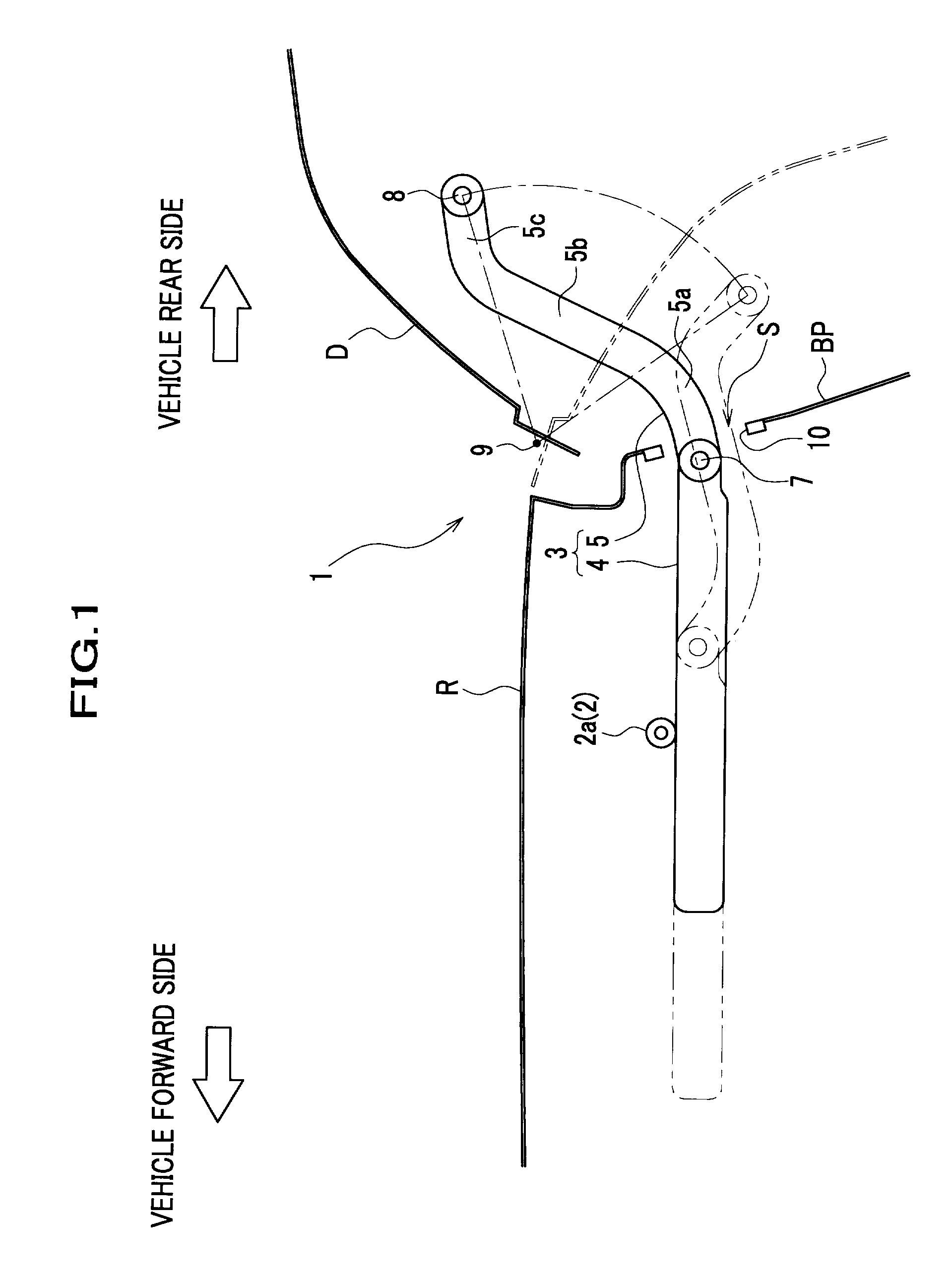
[0007]By the above, an arrangement with only a link member itself, that is, with only a few numbers of parts can be achieved. And along with this, deflection width size of a member can be made small, for example the interference degree of the load loaded into the circumference of opening and a link member can be reduced. Also, when a through hole is prepared for the link member to be inserted, the size of the through hole can be made small. Furthermore, since the link member moves so that a parabolic curve may be drawn without being regulated by the motion on the arc centering on an axial pin, the moving range in vehicles compartment can be made small as much as possible, to enable an effective use of the space of the vehicles compartment. Whereby, it is easily adapted to the existing vehicles having restricted use space.
[0009]By the above, an arrangement with only a link member itself, that is, with only a few numbers of parts can be achieved. And along with this, deflection width size of a member can be made small, for example the interference degree of the load loaded into the circumference of the opening and a link member can be reduced. Also, when a through hole is prepared for the link member to be inserted, the size of the through hole can be made small. Furthermore, since the link member moves so that a parabolic locus may be traced without being regulated by the motion on the arc centering on an axial pin, the moving range in vehicles compartment can be made small as much as possible, to enable an effective use of the space of the vehicles compartment. Whereby, it is easily adapted to the existing vehicles having a restricted use space. Furthermore by formation of a straight portion, since the connection part of a link member and a door is spaced apart from a rotation center of the door, a driving force by a driving mechanism required for an opening and closing of the door can be small. Also, since a connection part will be located in the space opened comparatively wide, the flexibility of a design of the circumference of a connection part spreads, and assembling work also becomes easy.
[0010]Moreover, the link member, the slider member and the door are connected by 3-dimensional joint mechanism, such as ball joint or a universal joint. This device permits a 3-dimensional rotation as well as a rotation to the rotating direction of a door only. The variation in size of a mounting device in the vehicle body and the door can be thus absorbed, to allow a smooth opening-and-closing operation of a door. Moreover, since the internal variation of a driving mechanism is also absorbable, the transfer efficiency of the driving force to a slider member can also be raised.
[0011]Furthermore, by employment of the arrangement in such a manner that a connection part of the link member and the slider member is inwardly disposed from the opening, with the door fully opened, good appearance can be presented and the influence of the rainstorm to the connection part can be reduced as much as possible.

Problems solved by technology

This pushed up the number of parts and posed a problem that accuracy in mounting process is hard to obtain.
In addition, space for securing the rotation range of a free end portion of the arm member is needed, to thereby pose another problem that vehicles compartment becomes narrower correspondingly.

Method used


Image

  • Vehicle door open-close device
  • Vehicle door open-close device
  • Vehicle door open-close device

Examples


Embodiment Construction

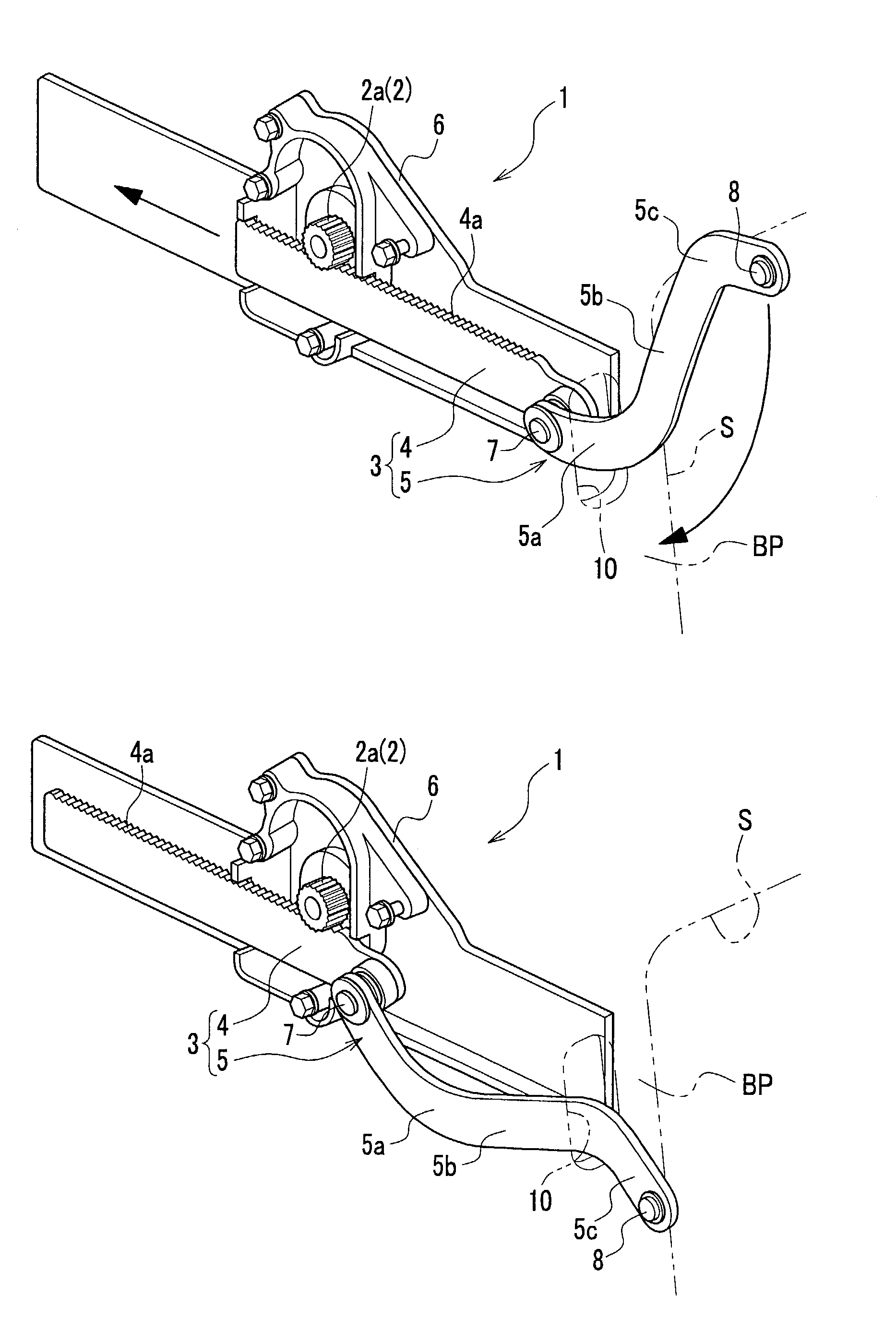
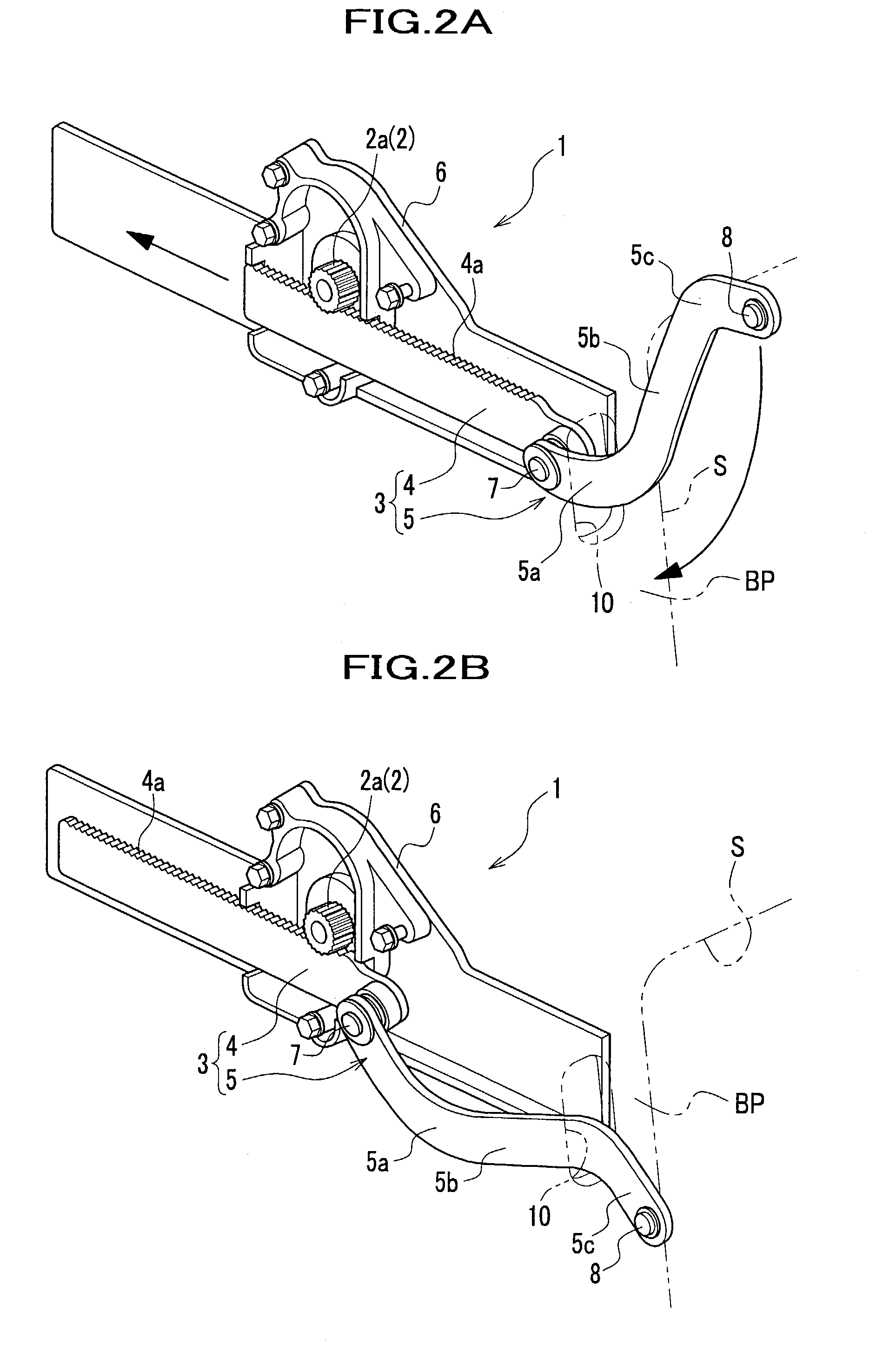
[0015]Preferred embodiment of the invention will now be explained with reference to the drawings. FIG. 1 is an explanatory side view showing a door open-close device, and FIG. 2 is a perspective view of the same, wherein door full-opening-state is represented in FIG. 2A, and door full-closing-state is represented in FIG. 2B.

[0016]A door open-close device adapted to a back door (referred as merely door hereinafter) D of a wagon vehicle as one mode of the invention is shown in FIG. 1. A door open-close device 1 which adopts a door open-close device of this invention will now be explained hereinafter. A door open-close device 1 has a driving mechanism 2 positioned within a vehicle compartment (indicating a part surrounded by a vehicle rear circumferential edge panel BP shown in FIG. 1, also see FIG. 2) and an operation transfer mechanism 3 to interconnect the driving mechanism 2 and door D.

[0017]An electric motor (not shown) etc. is used as a driving mechanism 2. An operation transfer ...


PUM


Abstract

A vehicle door open-close device which makes it possible to achieve a reduction in numbers of parts and also make the deflection width size of a member 5 small, to thereby allow an effective use of a vehicle compartment to be aimed at, is produced, comprising a driving mechanism positioned inwardly from a door opening, an operation transfer mechanism to connect this driving mechanism and the vehicle door, the operation transfer mechanism being equipped with a slider member reciprocatingly and linearly moving by the aid of the driving means, and a link member connecting this slider member and the vehicle door, wherein the link member is rotatably connected to the slider member and the vehicle door, and the link member includes a straight portion and a curved portion outwardly and protrudingly curved away from a center of rotation of the vehicle door, and a straight portion 5b formed in substantially straight line in a connection part 8. And in a process of fully-opening-state or fully-closing-state of the door, the curved portion passes across the door opening seen from the rotation axis direction.

Description

FIELD OF THE INVENTION[0001]The present invention relates to a vehicle door open-close device.BACKGROUND OF THE INVENTION[0002]As an open-close equipment which opens and closes the back door of vehicles by power, JP-A-2000-335245 proposes a technology wherein a rack axis is moved by an electric motor and an arm member fixed to the back door is driven through a link member connected to the rack axis, so as to open-and-close the back door.[0003]This technology is arranged in such a manner that in case where a through hole for an insertion of an arm member is prepared, the arm member is arcuately formed centering on the axial center of the back door, in order to make the size of this through hole small as much as possible, that is, in order to make the deflection width size of the arm member small, and the arm member is fixed to the back door.[0004]According to the above-described conventional technology, circumferential edge of an arm member in a vehicle compartment also arcuately mov...

Claims


Application Information

Patent Timeline
Patent Type & Authority Patents(United States)
IPC IPC(8): E05F15/10B60J5/10E05F15/12
CPCE05F15/63E05F15/619E05Y2201/722E05Y2900/546
Inventor IHASHI, YOSHITOMO
Owner HONDA MOTOR CO LTD
Learn More