Methods and apparatus for twist bend coupled (TCB) wind turbine blades

a technology wind turbine blades, which is applied in the field of wind turbine blades, can solve the problems of low research devoted to the study of the reaction of laminates used in the manufacturing of rotor blades to shear fatigue and other problems, and achieve the effect of increasing the energy capture power coefficient of the wind turbin

Active Publication Date: 2006-10-10
GENERAL ELECTRIC CO
View PDF5 Cites 77 Cited by
  • Summary
  • Abstract
  • Description
  • Claims
  • Application Information

AI Technical Summary

Benefits of technology

[0009]In some aspects, the present invention therefore provides a method for controlling a wind turbine having twist bend coupled rotor blades on a rotor mechanically coupled to a generator. The method includes determining a speed of a rotor blade tip of the wind turbine, measuring a current twist distribution and current blade loading, and adjusting a torque of a generator to change the speed of the rotor blade tip to thereby increase an energy capture power coefficient of the wind turbine.
[0011]In still other aspects, the present invention provides a wind turbine having twist bend coupled rotor blades on a rotor mechanically coupled to a generator. The wind turbine also has a controller that is configured to determine a speed of a tip of a rotor blade, measure a current twist distribution and current blade loading, and adjust a torque of the generator to change the speed of the rotor blade tip to thereby increase an energy capture power coefficient of the wind turbine.
[0013]It will be appreciated that configurations of the present invention not only provide wind turbines with greater energy capture, but also mitigate risks associated with shear fatigue of laminates used in twist bend coupled rotor blades.

Problems solved by technology

Within a twist-bend coupled section of a rotor blade that is made of laminate material, the laminates of the blade undergo shear fatigue resulting from continuous passive pitching.
This fatigue presents a risk to TBC technologies.
However, very little, if any, research has been devoted to the study of how laminates used in the manufacturing of rotor blades respond to shear axis fatigue.
Tip speed ratio is known in the industry and is generally a limiting factor in blade rotational design.
This limit results from aerodynamic noise.
Energy loss still occurs at other wind speeds.

Method used


Image

  • Methods and apparatus for twist bend coupled (TCB) wind turbine blades
  • Methods and apparatus for twist bend coupled (TCB) wind turbine blades
  • Methods and apparatus for twist bend coupled (TCB) wind turbine blades

Examples


Embodiment Construction

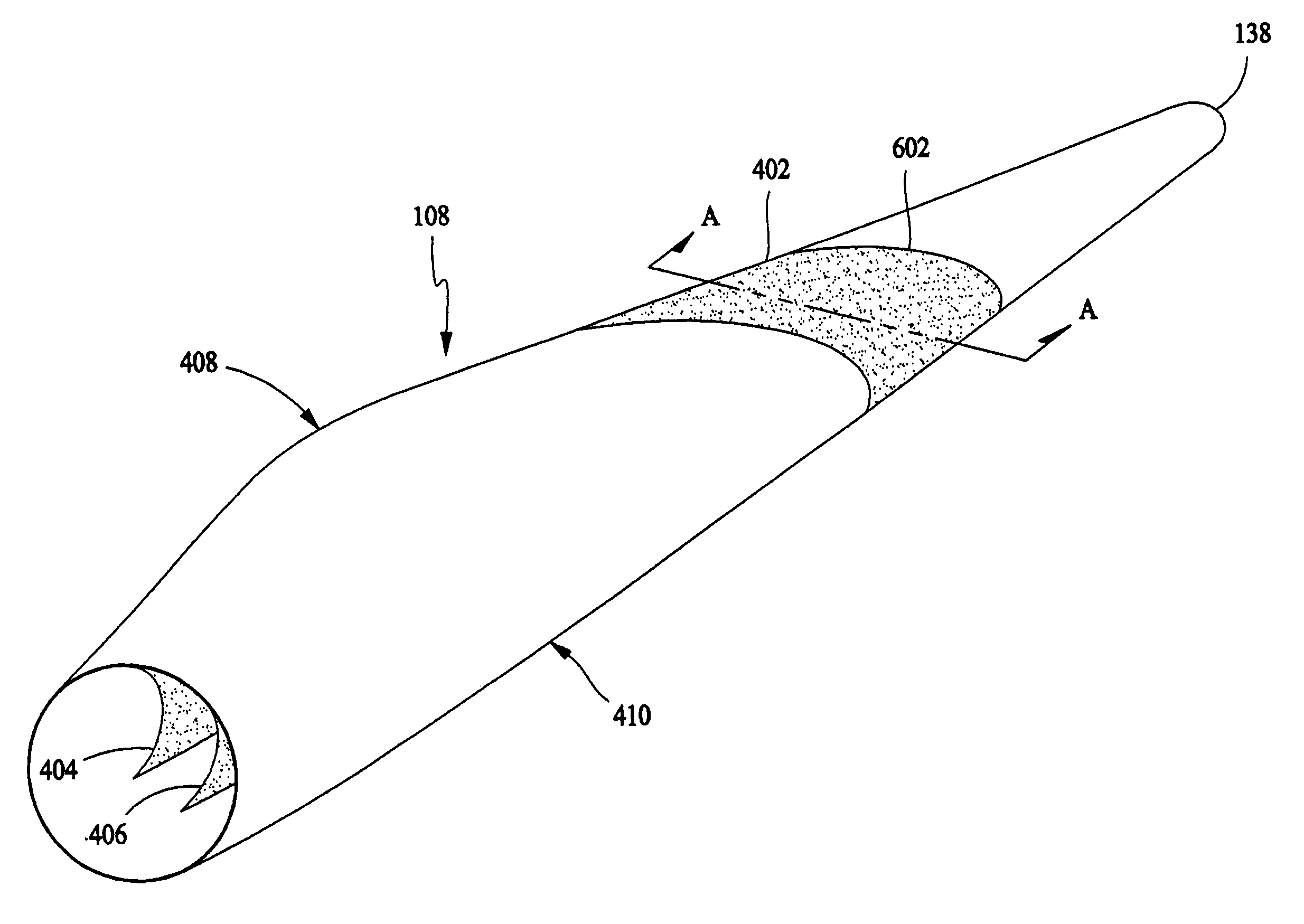
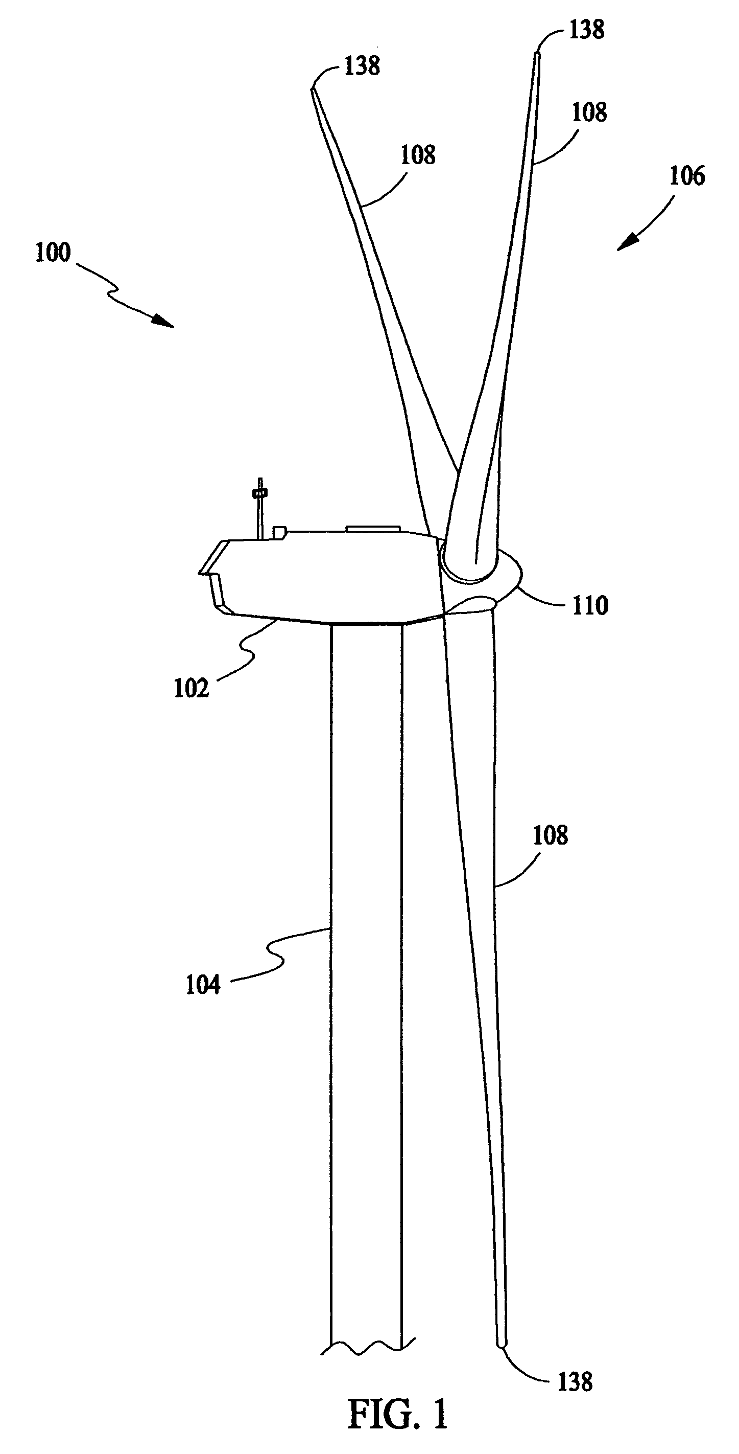
[0020]In some configurations and referring to FIG. 1, a wind turbine 100 comprises a nacelle 102 housing a generator (not shown in FIG. 1). Nacelle 102 is mounted atop a tall tower 104, only a portion of which is shown in FIG. 1. Wind turbine 100 also comprises a rotor 106 that includes one or more rotor blades 108 attached to a rotating hub 110. Although wind turbine 100 illustrated in FIG. 1 includes three rotor blades 108, there are no specific limits on the number of rotor blades 108 required by the present invention.

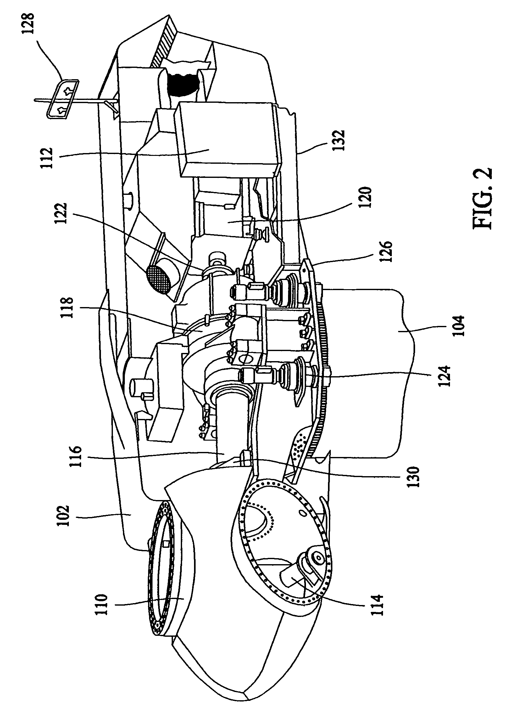
[0021]In some configurations and referring to FIG. 2, various components are housed in nacelle 102 atop tower 104 of wind turbine 100. The height of tower 104 is selected based upon factors and conditions known in the art. In some configurations, one or more microcontrollers within control panel 112 comprise a control system are used for overall system monitoring and control including pitch and speed regulation, high-speed shaft and yaw brake application, yaw and pu...


PUM


Abstract

A method for controlling a wind turbine having twist bend coupled rotor blades on a rotor mechanically coupled to a generator includes determining a speed of a rotor blade tip of the wind turbine, measuring a current twist distribution and current blade loading, and adjusting a torque of a generator to change the speed of the rotor blade tip to thereby increase an energy capture power coefficient of the wind turbine.

Description

STATEMENT REGARDING FEDERALLY SPONSORED RESEARCH & DEVELOPMENT[0001]The U.S. Government has certain rights in this invention as provided for by the terms of Contract No. DE-AC36-83CH10093, Subcontract No. ZAM-7-13320-26 awarded by the Department of Energy / Midwest Research Institute, National Renewable Energy Laboratory Division.BACKGROUND OF THE INVENTION[0002]This invention relates generally to wind turbines, and more particularly to methods and apparatus for increasing energy capture and for controlling twist angles of blades resulting from passive twist bend coupling.[0003]Recently, wind turbines have received increased attention as environmentally safe and relatively inexpensive alternative energy sources. With this growing interest, considerable efforts have been made to develop wind turbines that are reliable and efficient.[0004]Generally, a wind turbine includes a rotor having multiple blades. The rotor is mounted within a housing or nacelle, which is positioned on top of a t...

Claims


Application Information

Patent Timeline
Patent Type & Authority Patents(United States)
IPC IPC(8): F03D7/04
CPCF03D7/0228F05B2240/131F05B2270/1095F05B2270/402Y02E10/723Y02E10/72
Inventor MOROZ, EMILIAN MIECZYSLAWLEMIEUX, DAVID LAWRENCEPIERCE, KIRK GEE
Owner GENERAL ELECTRIC CO
Why Eureka
Try Eureka