Compressed air system and method of control

a technology of compressed air and air compressor, applied in the direction of pump control, positive displacement liquid engine, pump, etc., can solve the problems of high duty cycle of air compressor motor, high cost, size and weight constraints,

Active Publication Date: 2006-10-10
GE GLOBAL SOURCING LLC
View PDF16 Cites 16 Cited by
  • Summary
  • Abstract
  • Description
  • Claims
  • Application Information

AI Technical Summary

Problems solved by technology

This is important because the electrical and mechanical transients that are generated during a motor/compressor start-up event may severely challenge the compressor motor and associated electrical contacts.
A larger, higher-pressure reservoir will reduce the duty cycle of the compressor motor, but there are associated cost, size and weight constraints that must be considered.
However, in spite of the optimization of system design, there have bee

Method used


Image

  • Compressed air system and method of control
  • Compressed air system and method of control
  • Compressed air system and method of control

Examples


Embodiment Construction

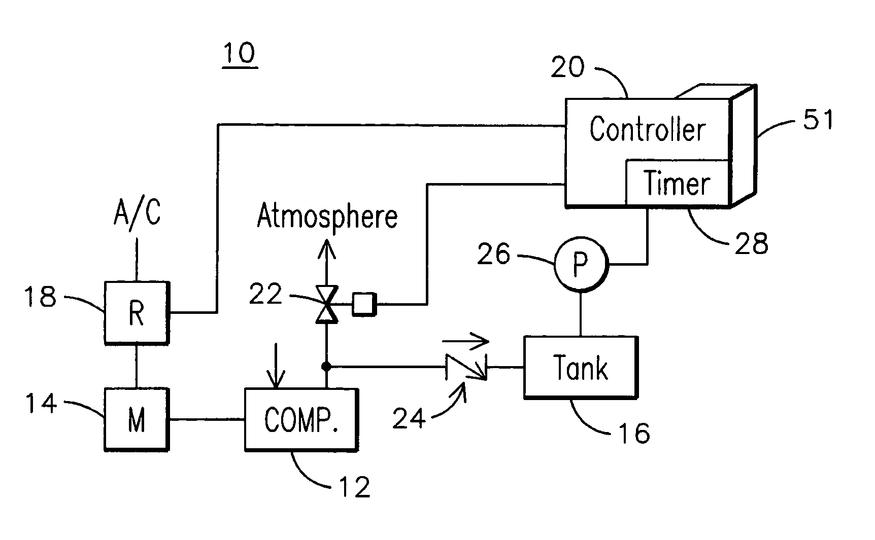
[0009]An improved compressed air system 10 as may be used on a locomotive or other application is illustrated in FIG. 1. The system includes a compressor 12 that is driven by an electrical motor 14 to provide a flow of compressed air to a reservoir or storage tank 16. A power supply may be coupled through a relay 18 or other such electrical switching device to energize the motor 14. The relay 18 is selectively positioned to energize or to de-energize the motor 14 in response to a motor control signal generated by a controller 20. The flow of compressed air is directed to the reservoir 16 when a bypass valve 22 in the compressed air supply line is closed, i.e. in a compressor loaded position or mode. The flow of compressed air is vented to atmosphere when the bypass valve 22 is open, i.e. in a compressor unloaded position or mode. A check valve 24 prevents compressed air in the tank 16 from escaping through the compressed air supply line. The controller 20 provides a control signal t...


PUM


Abstract

A compressed air system, wherein a decision to de-energize a compressor motor is made with consideration of the likely need for the operation of the compressor at a future point in time. A rate of pressure decay in an air reservoir may be extrapolated over a predetermined time period to predict the need for operation of the compressor within the time period. If operation of the compressor is predicted to be needed within the time period, the compressor is allowed to continue to run in an unloaded mode beyond a normal cool down period.

Description

[0001]This application claims priority to a provisional application filed on Mar. 6, 2003, having application No. 60 / 452,621, which is incorporated herein by reference.FIELD OF THE INVENTION[0002]This invention relates generally to compressed air systems, and more particularly to a compressed air system for a locomotive.BACKGROUND OF THE INVENTION[0003]Compressed air systems are used to provide energy for driving a variety of devices in a variety of applications. One such application is a railroad locomotive where compressed air is used to power locomotive air brakes and pneumatic control systems.[0004]A typical compressed air system will include a reservoir for storing a volume of compressed air. A motor-driven compressor is used to maintain the air pressure in the reservoir within a desired range of pressures. The reservoir pressure may be higher than the demand pressure for a device supplied by the system, in which case a pressure regulator may be used to reduce the pressure supp...

Claims


Application Information

Patent Timeline
IPC IPC(8): F04B49/03F04B49/08F04B41/02F04B49/06
CPCF04B41/02F04B49/03F04B49/06
Inventor DEAN, JASON ARTHURLINEBACH, MARK ALANBLILEY, RICHARD GERALDPELKOWSKI, STEPHEN MATTHEWKISAK, JEFFREY JAMES
Owner GE GLOBAL SOURCING LLC
Why Eureka
Try Eureka