Bonded elastomeric connector

a technology of elastomeric connectors and bonded elastomers, which is applied in the direction of coupling device connections, coupling device details, and connection contact member materials, etc., can solve the problems of limiting the size of pogo pin connectors, traditional connector designs become inadequate, and the size of connectors must also become smaller

Inactive Publication Date: 2006-10-10
TE CONNECTIVITY CORP
View PDF11 Cites 18 Cited by
  • Summary
  • Abstract
  • Description
  • Claims
  • Application Information

AI Technical Summary

Problems solved by technology

The aforementioned connector solutions have certain shortcomings, such as, for instance, they require custom tooling to manufacture and have long lead times. In particular, as electronic packages become progressively smaller, the size of the connectors must also become smaller and in many instances, the traditional connector designs become inadequate.
In particular, there is a limit to how small a pogo pin connector can be made.
Not only are there size limits for the pogo pin components, but at its limits, the deflection range becomes insufficient.
In addition, the connector becomes even more costly as the size is reduced.
It remains a challenge to provide a low profile low cost connector that is easily modified for multiple applications, that requires little tooling, and may be produced with short lead times.

Method used


Image

  • Bonded elastomeric connector
  • Bonded elastomeric connector
  • Bonded elastomeric connector

Examples


Embodiment Construction

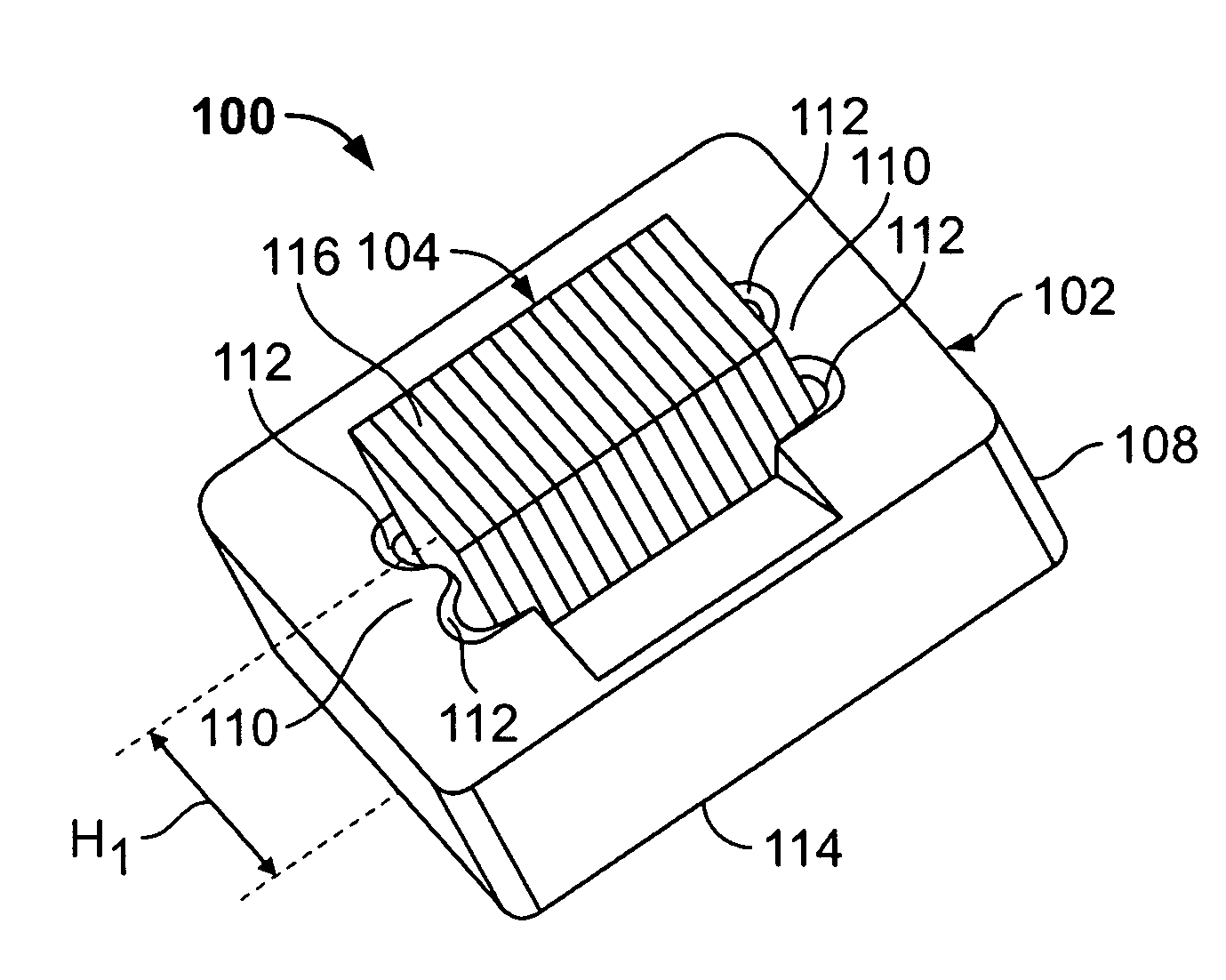
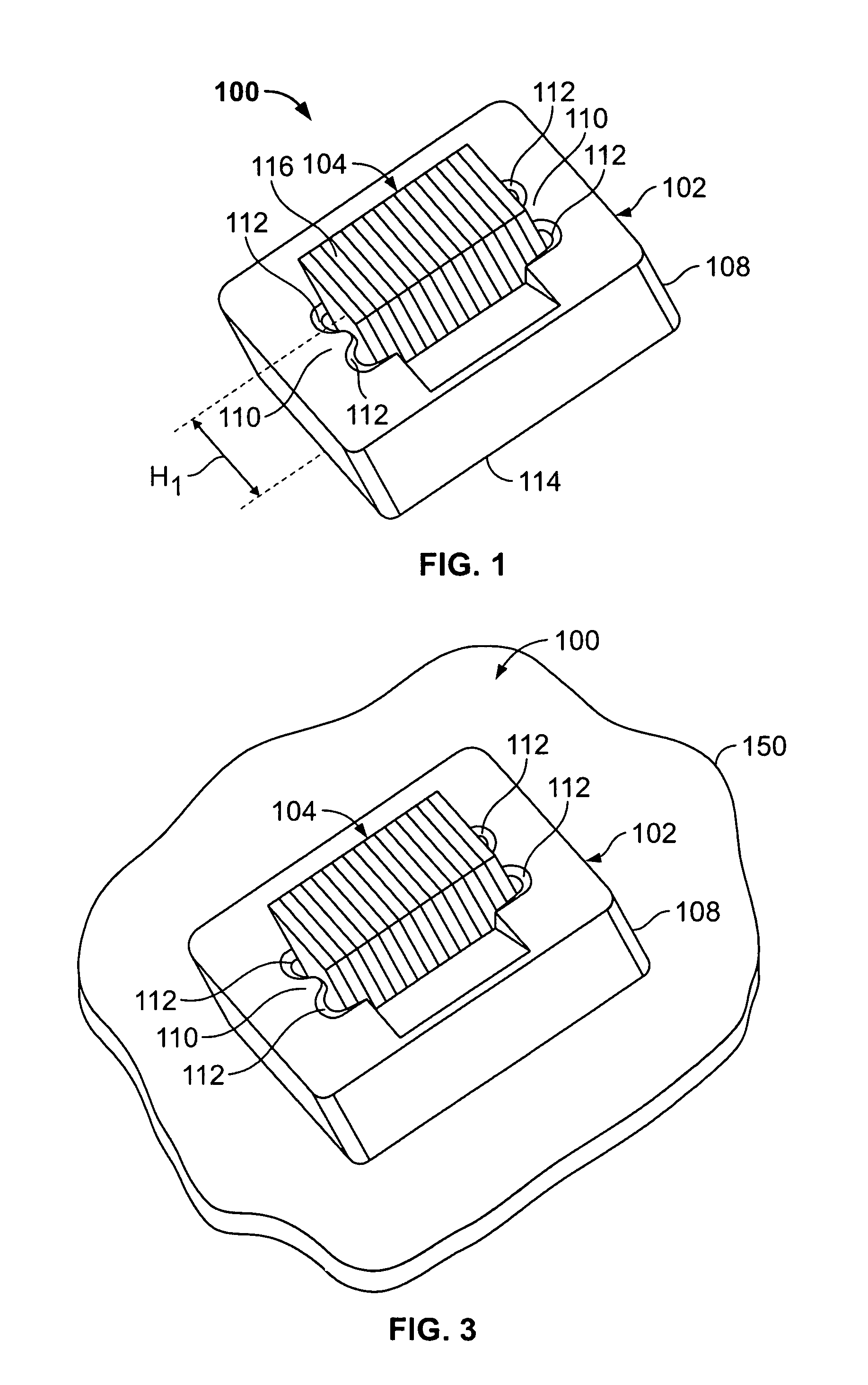
[0013]FIG. 1 is a perspective view of a bonded elastomeric connector 100 formed in accordance with an exemplary embodiment of the present invention. The connector 100 includes a holder 102 and an elastomeric member 104. The holder 102 includes a body 108 that is formed with positioning ribs 110 and relief areas 112. The elastomeric member 104 is mounted in the holder 102 between the positioning ribs 110. In the illustrated assembled connector 100, the elastomeric member 104 is bonded to the holder 102 forming an integrated assembly. The connector 100 has an overall height H1 from a first mating surface at a base 114 of the holder 102 to an upper contact surface 116 of the elastomeric member 104.

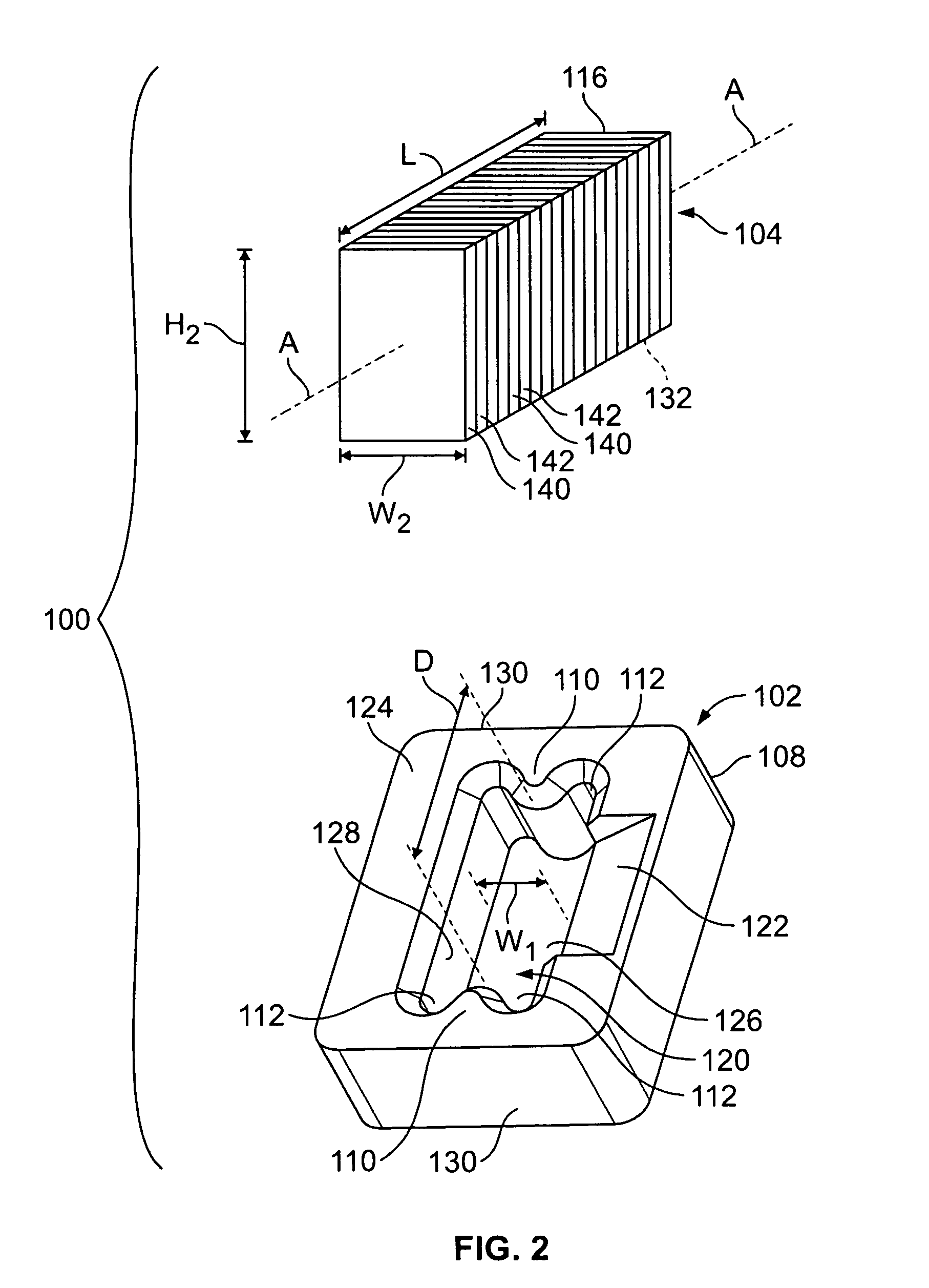
[0014]FIG. 2 is an exploded view of the elastomeric connector 100. The body 108 includes a pocket 120 that receives the elastomeric member 104. The positioning ribs 110 are formed at opposite ends of the pocket 120, a distance D apart. The pocket 120 has a width W1. A receiving area 122 is pr...


PUM

PropertyMeasurementUnit
height H1aaaaaaaaaa
conductiveaaaaaaaaaa
electrical currentaaaaaaaaaa

Abstract

An electrical connector includes a holder configured to be mechanically and electrically connected to a circuit board. The holder has a surface that is at least partially conductive. A conductive elastomeric member is mounted in the holder and electrically connected to the at least partially conductive surface of the holder. The at least partially conductive surface is configured to convey electrical current between the elastomeric member and the circuit board.

Description

BACKGROUND OF THE INVENTION[0001]The invention relates generally to electrical connectors and, more particularly, to a bonded elastomeric connector for making connections between substrates.[0002]Many electronic applications utilize single contact connections to make a connection between substrates. For example, in a mobile phone application, a single contact connector may be used for making a grounding connection between two circuit boards. Typically, pogo pin type connectors or stamped and formed connectors are used for making such single contact connections. In addition, multiple pogo pin or stamped and formed connectors are often used to make connections to components such as speakers, ringers, or vibration motors and the like.[0003]The aforementioned connector solutions have certain shortcomings, such as, for instance, they require custom tooling to manufacture and have long lead times. In particular, as electronic packages become progressively smaller, the size of the connecto...

Claims


Application Information

Patent Timeline
Patent Type & Authority Patents(United States)
IPC IPC(8): H01R4/58
CPCH01R13/2414
Inventor PUPKIEWICZ, EDWARD JOSEPHWOZNIAK, BOHDAN PETRO
Owner TE CONNECTIVITY CORP
Why Eureka
Try Eureka